09/2007
7-4
Phaser 8860/8860MFP Service Manual
Plug/Jack Locations
Initial Issue
Wiring Data
Plug/Jack Locations
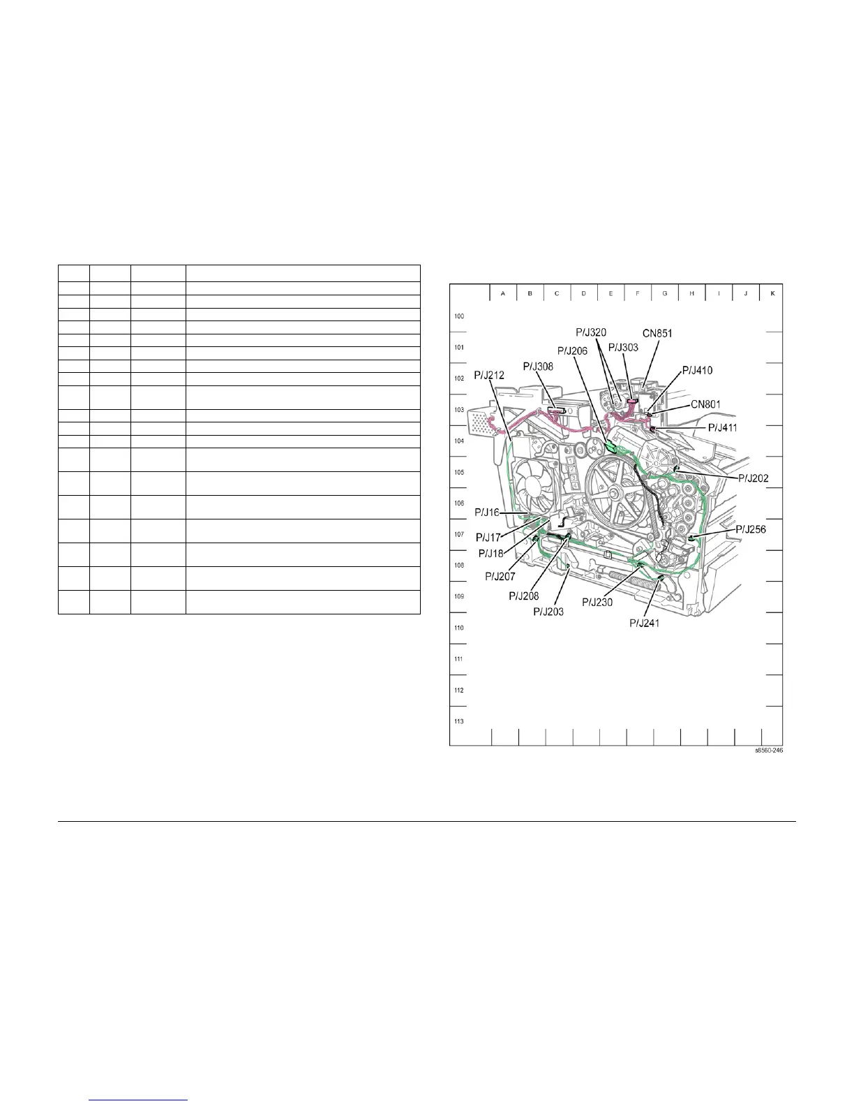
Figure 1 8860MFP Left Side P/J Locations
410 Figure 1 F-103 Connects the Speaker to the Exit Module Harness.
411 Figure 1 G-104 Connects the Exit Door Interlock to the Exit Module Harness.
600 Figure 12 G-107 Connects the Control Panel to the I/O Board
600 Figure 9 B-108 Connects the Paper Size Switch to the I/O Board.
610 Figure 9 C-108 Connects the I/O Board to the Front Door/Tray 1 Assy.
650 Figure 3 E-109 Connects Front Door/Tray 1 to the I/O Board.
680 Figure 9 H-105 Connects the I/O Board to the Exit Module.
840 Figure 9 E-107 Connects the I/O Board to the Electronics Module.
860 Figure 9 G-106 Connects the Drum Maintenance Pivot Plate to the I/O
Board.
860 Figure 11 G-103 Connects the Preheater Board to the I/O Board
870 Figure 9 G-106 Connects the Drum Temp Sensor to the I/O Board.
910 Figure 9 C-109 Connects the Ink Loader Sensors to the I/O Board.
CN1 Figure 7 G-107 Connects the Exit Module Control Board to the Scanner
Power Supply.
CN2 Figure 7 A-106 Connects the Exit Module Control Board to the Exit Module
sensors.
CN4 Figure 7 D-108 Connects the Exit Module Control Board to the Exit Module
motors.
CN5 Figure 7 A-107 Connects the Scanner Power Supply Fan to the Exit Module
Control Board.
CN801 Figure 2 E-102 Connects the right Output Tray Full Sensor to the Exit Mod-
ule harness.
CN802 Figure 1 G-103 Connects the left Output Tray Full Sensor to the Exit Module
harness.
CN851 Figure 1 F-102 Connects the Scanner Detect Sensor to the Exit Module
Harness.
Table 1 Plug / Jack Location List
P/J Map Coordinates Remarks