09/2007
8-15
Phaser 8860/8860MFP Service Manual
Image Output Terminal
Theory of Operation
Initial Issue
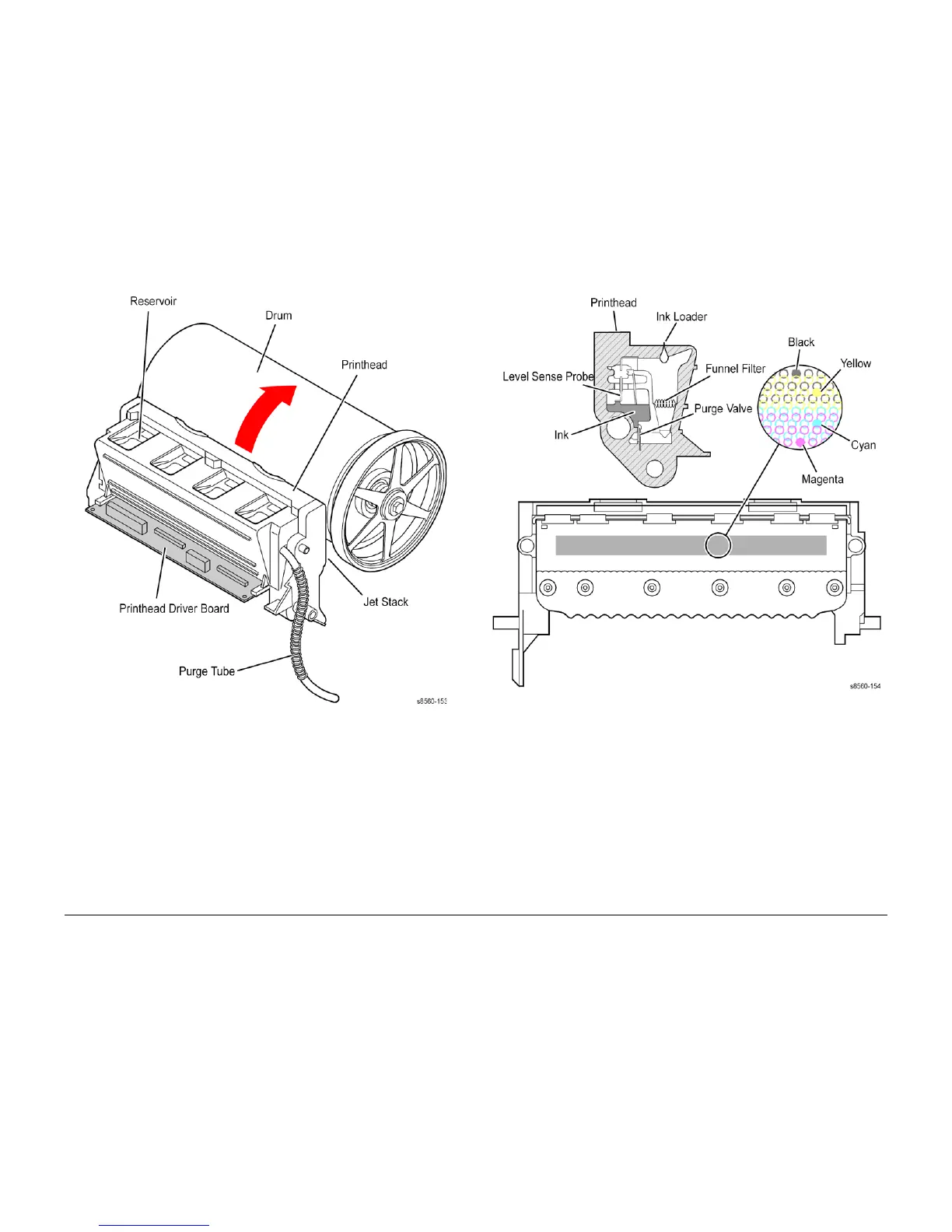
Figure 11 Printhead Components
Figure 12 Printhead Detail
The Printhead’s jet stack is fabricated from a stack of chemically etched steel plates which are
brazed together to form the jet array. Channels formed by the stacked plates route ink past the
1236 individual, piezo-electric crystal-driven diaphragms, which force the ink in droplets out the
1236 corresponding nozzles. Looking at the Printhead face, the nozzles are arranged in 12
rows, in color order KYKYKYCMCMCM, where K = black, Y = yellow, C = cyan, and M =
magenta. During the printing process, the Printhead would only have to travel approximately 14
pixels horizontally to provide complete coverage. However, the Printhead travels much further,
depending on print resolution, to interlace each jet with the output of neighboring jets.
The jet array is bonded to a cast aluminum ink reservoir. The reservoir supplies the molten ink
to the jet array. Heaters in the reservoir and the jet array keep the ink in a liquid state.
 Loading...


