Charging unit and component
5-25
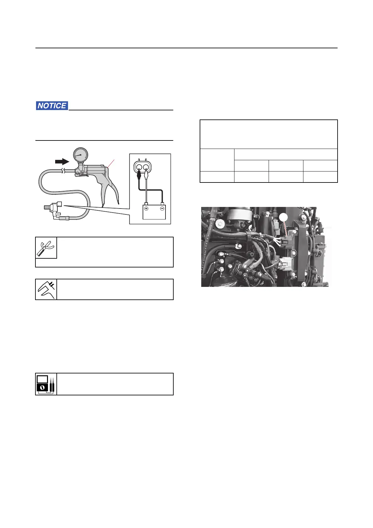
c. Check that the vapor shut-off valve
opens and the negative pressure is re-
leased when the battery leads are
connected to the vapor shut-off valve
terminals.
Connect the battery leads to the vapor
shut-off valve terminals for only a few sec-
onds.
d. Disconnect the special service tool.
e. Install the vapor shut-off valve.
3. Measure:
• Vapor shut-off valve resistance
Out of specification Replace.
a. Disconnect the vapor shut-off valve
coupler.
b. Measure the resistance between the
vapor shut-off valve terminals.
c. Connect the vapor shut-off valve cou-
pler.
Charging unit and component
Checking the lighting coil (stator as-
sembly)
1. Measure:
• Lighting coil output peak voltage
Out of specification
Measure the light-
ing coil resistance.
a. Disconnect the lighting coil coupler
“a
”.
b. Connect the special service tool “1”.
c. Remove the clip from the engine shut-
off sw
itch.
d. While cranking the engine, measure
the peak voltage.
e. Insert the clip into the engine shut-off
switch.
f. Start the engine, and then measure
the peak voltage at the specified en-
gine speed.
Vacuum/pressure pump gauge set
“1
”
90890-06945
Specified negative pressure
67.0 kPa (0.67 kgf/cm², 9.7 psi)
Resistance
30.0–34.0
1
Lighting coil output peak voltage
(reference data)
White (W)–White (W)
r/min
Unloaded
Cranking 1500 3500
DC V 11.1 40.7 93.7