Camshaft and valve
7-34
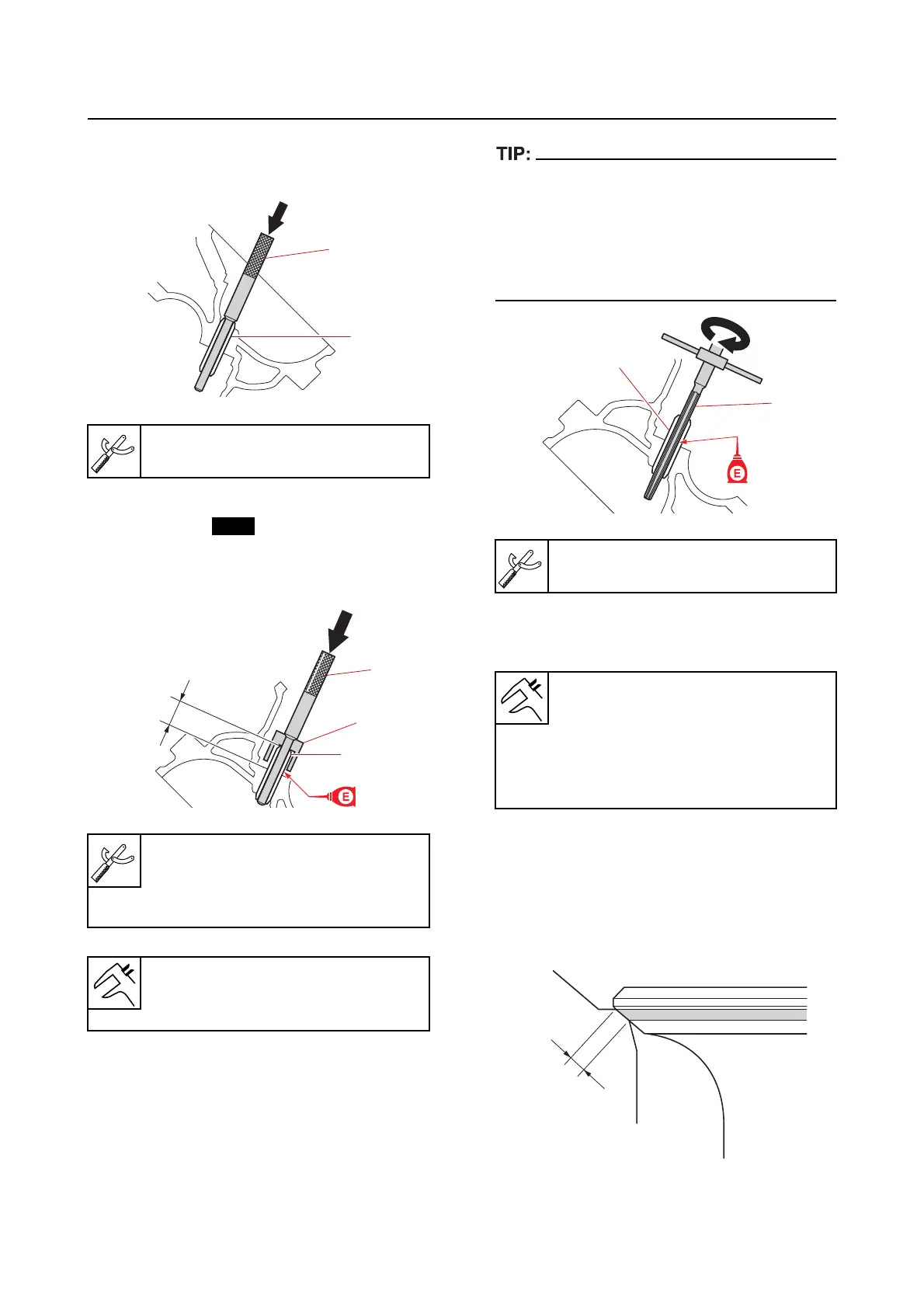
1. Remove:
• Valve guide “1” (from the combustion
chamber side)
2. Install:
• Valve guide
a. Install a new valve guide “1” to the
specified in
stallation height “a” from
the camshaft side.
3. Ream:
• Valve guide “1”
• To ream the valve guide, turn the valve guide
reamer clockwise.
• When removing the valve guide reamer, do
not turn it counterclockwise.
• After reaming the valve guide, make sure to
clean it.
4. Measure:
• Inside diameter
Checking the valve seat
1. Measure:
• Contact width “a”
Not seated properly/out of specification
Reface.
Uneven Check
the valve guide.
Valve guide remover/installer “2”
90890-06801
Valve guide remover/installer “2”
90890-06801
Valve guide installer “3”
90890-06810
Installation height
16.00–16.40 mm (0.6299–0.6457
in)
1
2
1
2
3
a
Valve guide reamer “2”
90890-06804
Inside diameter IN
5.504–5.522 mm (0.2167–0.2174
in)
Inside diameter EX
5.504–5.522 mm (0.2167–0.2174
in)
2
1
a