Cylinder head
7-28
Removing the cylinder head
1. Remove:
• Cylinder head
Do not scratch or damage the mating sur-
faces of the cylinder head and cylinder
block.
Checking the cylinder head bolt
1. Measure:
• Cylinder head bolt (M10) diameter
Out of specification Replace.
a. Measure the diameters “a” and “b” of
the cylinder head
bolt (M10) at the
specified measuring points “c” and “d”.
Checking the cylinder head anode
1. Check:
• Anode
Eroded (1/2 or more) Replace.
There is grease, oil, or scales Clean.
Do not apply grease, oil, or paint to the an-
odes.
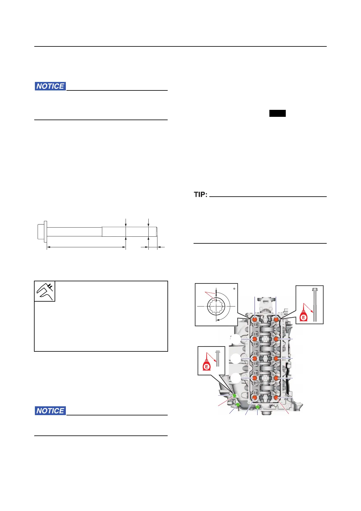
Installing the cylinder head
Before installing the cylinder head, check the
cylinder head bolts. See “Checking the cylinder
head bolt” (7-28).
1. Install:
• Dowel pin
• Cylinder he
ad gasket
• Cylinder he
ad
2. Tighten:
• Cylinder he
ad bolt (M10)
• Cylinder he
ad bolt (M8)
a. Tighten the cylinder head bolts (M10)
“1
” to the specified torques in 3 stages
and in the order [1], [2], and so on.
In the third tightening stage for the cylinder
head bolts (M10) “1”, mark the bolts and cylin
-
der head with identification marks “a”, and then
tighten the
bolts 180 from the marks on the
cylinder head.
b. Tighten the cylinder head bolts (M8)
“2” to the specified torques in 2 stages
and in the order [11], [12], and so on.
Cylinder head bolt (M10) diameter
difference limit
“a” – “b” = Less than 0.17 mm (0.01
in)
Measuring point “c”: 10.0 mm
(0.39 in)
Measuring point “d”: 68.0 mm
(2.68 in)
2
1
[10][9]
[6]
[2]
[3]
[7]
[5]
[1]
[4]
[13]
[11]
[12]
[8]
a
180