Ignition unit and component
5-32
c. Measure the thermo sensor resis-
tance.
d. Install the thermo sensor. See “Oil
cooler” (7-25).
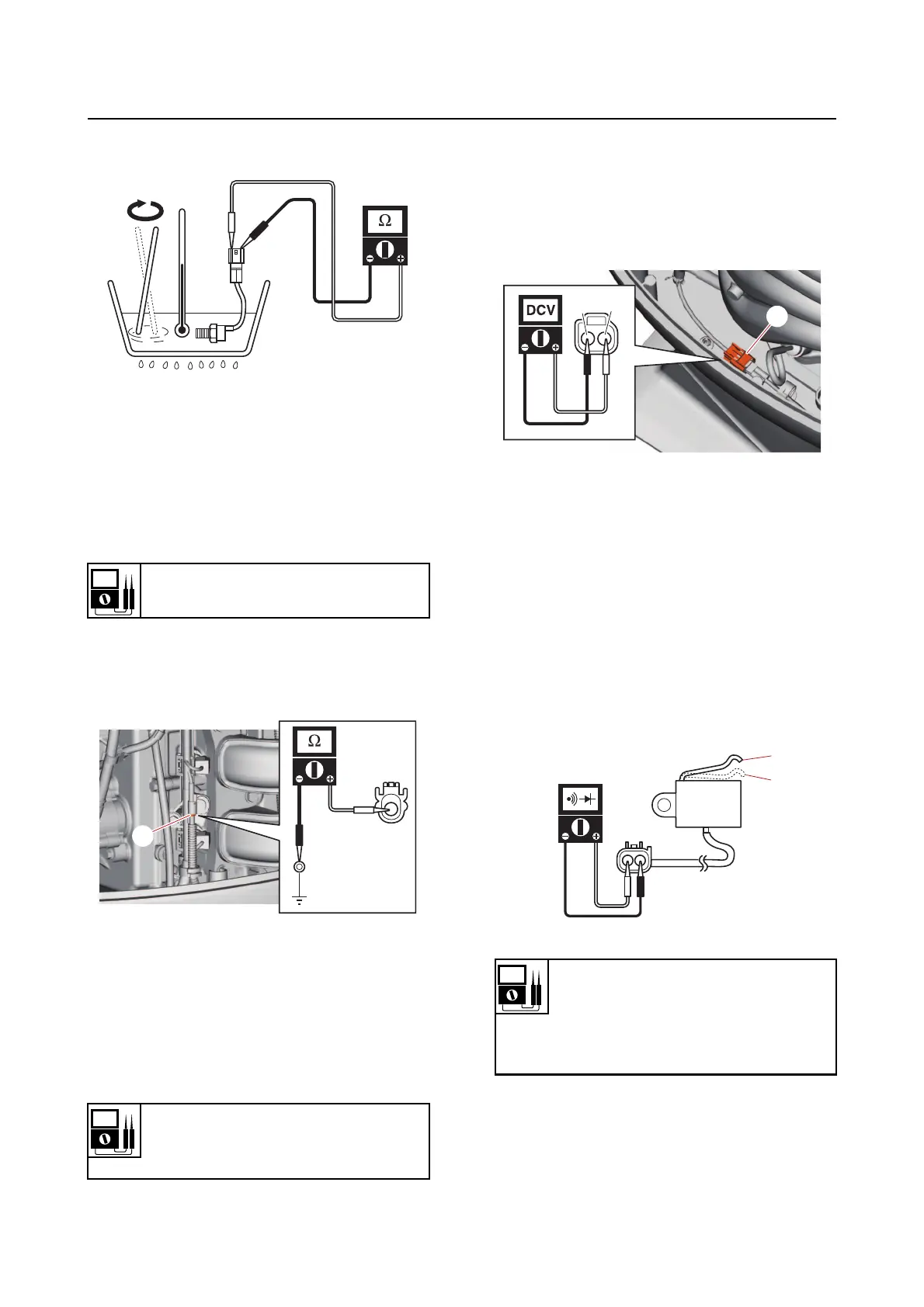
Checking the knock sensor
1. Measure:
• Knock sensor resistance
Out of specification Replace.
a. Disconnect the knock sensor coupler
“a”.
b. Measure the knock sensor resistance.
c. Connect the knock sensor coupler.
Checking the shift position switch
1. Measure:
• Shift position switch input vo
ltage
Out of specification Check the wire har-
ness for continuity.
a. Disconnect the shift position switch
coupler “a”.
b. Turn the engine start switch to ON,
and then measure the input voltage at
the shift position switch coupler.
c. Turn the engine start switch to OFF.
d. Connect the shift position switch cou-
pler.
2. Check:
• Shift position switch continuity
Out of specification Replace.
a. Remove the shift position switch.
b. Check the shift position switch for con-
tinuity.
c. Install the shift position switch. See
“Shift rod and shift bracket” (9-9).
Resistance
504–616 k
Input voltage
5 V
Blue/Yellow (L/Y)–Black (B)
a
Shift position switch continuity
No continuity
Switch position “a”
Continuity
Switch position “b”
L/Y
B
a
a
b