Crankcase
7-61
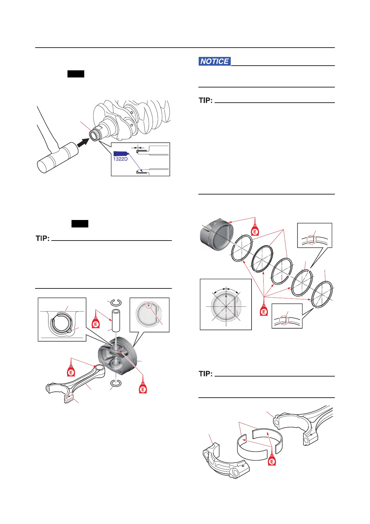
Assembling the cylinder block
1. Install:
• Coll
ar
a. Install a new collar “1” by striking it us-
ing a plastic hammer.
2. Assemble:
• Piston “1”
• Connecting rod “2”
• Piston pin “3”
• Cli
p “4”
• Face the protrusions “a” on the connecting
rod “2” in the same direction as the mark “b”
on the piston crown.
• Make sure that the clip “4” end is not aligned
with the groove “c” in the piston pin boss.
3. Install:
• Oil ring
• 2nd ring
• Top ring
a. Install the oil rings “1”, 2nd ring “2”,
and top ring “3”.
Do not scratch the pistons or break the pis-
ton rings.
• Make sure that the “2T” mark “a” on the 2nd
ring “2” and “1T” mark “b” on the top ring “3”
are facing up.
• Make sure that the piston rings move
smoothly.
• Do not deform the p
iston ring opening be-
yond the following specifications.
Oil ring: 11.7 mm (0.46 in)
2nd ring: 21.6 mm (0.85 in)
Top ring: 20.0 mm (0.79 in)
b. Offset the piston ring end gaps.
4. Install:
• Crankshaft pin bearing “1” (into the
con-
necting rod “2” and connecting rod cap “3”)
Install the crankshaft pin bearings in the origi-
nal positions.
1
b
a
c
1
2
3
4
4
4
1T
2T
#3
#4
#5
#1
#2
#5
#4
#3
#1
#2
45
°
45
°
a
b
1
2
3
3
1
2