Wiring diagram
A-7
Wiring diagram
How to use the wiring diagram
Composition of the wiring diagrams
The wiring diagram consists of five categories; “Engine control unit, fuel unit, and ignition unit (tiller han-
dle model)”, “Charging unit, starting unit, and PTT unit (tiller handle model)”, “Engine control unit, fuel
unit, and ignition unit (remote control model)”, “Charging unit, starting unit, and PTT unit (remote control
model)”, and “Control unit”.
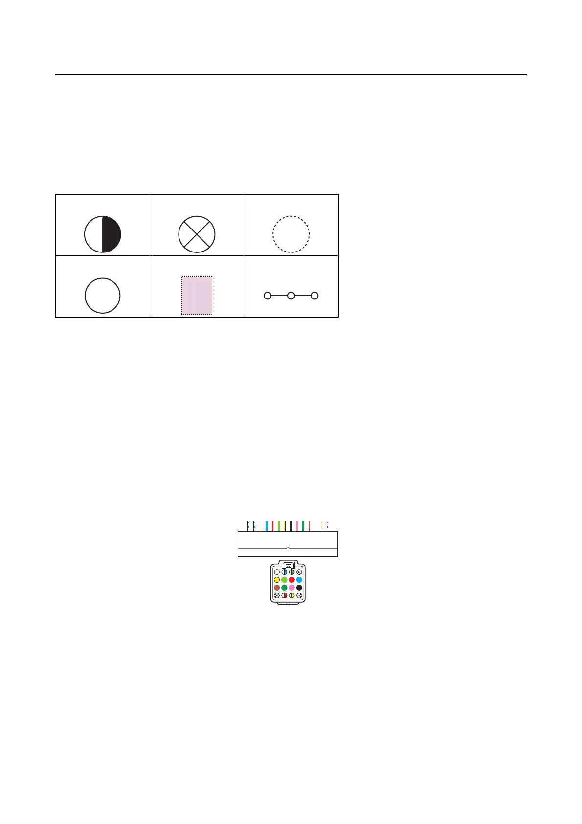
Legend symbols in the wiring diagrams
Terminal numbers
• Terminal numbers
are indicated for cases where terminal locations of wires are unclear.
• In
the coupler illustrations, only the rightmost and leftmost terminal numbers are indicated, and termi-
nal numbers between them are omitted.
1 2 3
4 5 6
1. Double colors wire
2. Not used (vacant)
3. A wire is not included in the selected wiring unit.
4. Alert buzzer
5. Optional parts
6. Continuity
2
3
1
4
5
6
7
8
9
10
11
12
13
14
15
16
4
8
12
16
1
5
9
13