Upper case (X-transom model)
9-17
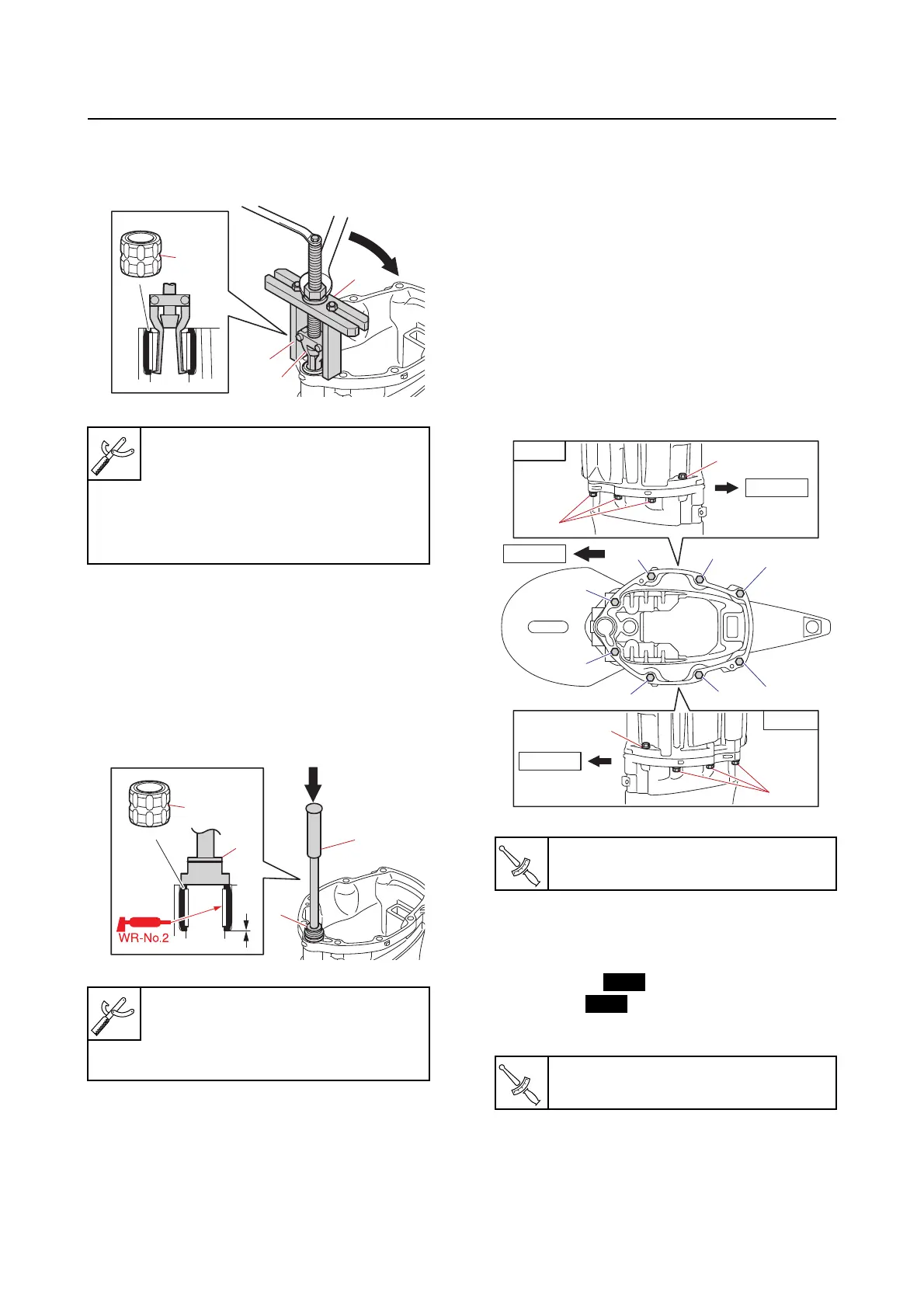
Disassembling the upper case
1. Remove:
• Drive
shaft bushing “1”
Checking the drive shaft bushing
1. Check:
• Drive shaft
bushing
Cracked/worn Replace.
Assembling the upper case
1. Install:
• Drive
shaft bushing “1”
2. Install:
• Rubber seal (to the oil pan assembly)
• Guide (to the oil pan assembly)
• Water pipe
• Rubber seal (to the oil pan assembly)
• Dowel pin
• Rubber seal (to the upper case)
• Upper case
3. Tighten:
• Upper case bolt
a. Tighten the upper case bolts “1” to the
specified tor
que in the order [1], [2],
and so on.
4. Install:
• Rubber seal
• Damper
• Plastic tie
• Gasket
• Drain bolt
Stopper guide plate “2”
90890-06501
Bearing puller assembly “3”
90890-06535
Stopper guide stand “4”
90890-06538
Needle bearing attachment “2”
90890-06611
Driver rod L3 “3”
90890-06652
Upper case bolt “1”
42 N·m (4.2 kgf·m, 31 lb·ft)
Drain bolt
27 N·m (2.7 kgf·m, 20 lb·ft)
STBD
PORT
Front
Front
Front
[2][1]
[4]
[3]
[6] [5]
[8]
[7]
1
1
1
1