Fuel pump assembly
6-10
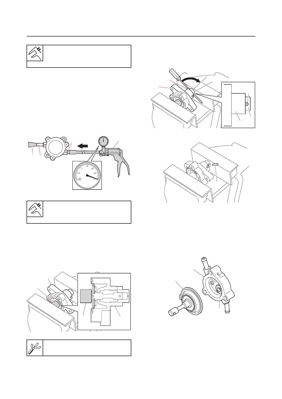
d. Connect the special service tool “1” to
the fuel pump outlet “a”.
e. Block the fuel pump inlet “b” using a
rubber plug “2”.
f. Apply the specified positive pressure,
and then check
that there is no air
leakage.
Disassembling the fuel pump assem-
bly
1. Remove:
• Pin
a. Compress the plunger spring using a
vise to
hold the fuel pump body “1”.
b. While holding fuel pump body “1” in
place, insert a
flathead screwdriver
into the hole “a” in the plunger “2” and
turn it 90.
c. Remove the pin “1”.
Checking the diaphragm and valve
1. Check:
• Diaphragm “1”
Torn/deformed/worn Replace.
• Valve “2”
Deformed/worn Replace
the fuel pump
body “3”.
Assembling the fuel pump assembly
Before assembling the fuel pump assembly,
clean the parts and soak the valves and dia-
phragm in gasoline to obtain prompt operation
of the fuel pump assembly.
Fuel inlet holding pressure (nega-
tive pressure)
30.0 kPa (0.30 kgf/cm², 4.4 psi)
Fuel outlet holding pressure (posi-
tive pressure)
196.0 kPa (1.96 kgf/cm², 28.4 psi)
Small end bearing installer “2”
90890-06528
a
b
1
2
1
1
2
3



 To Next Page