How to use this manual
0-7
How to use this manual
Manual format
The format of this manual has been designed to make service procedures clear and easy to under-
stand. Use the following information as a guide for effective and quality service.
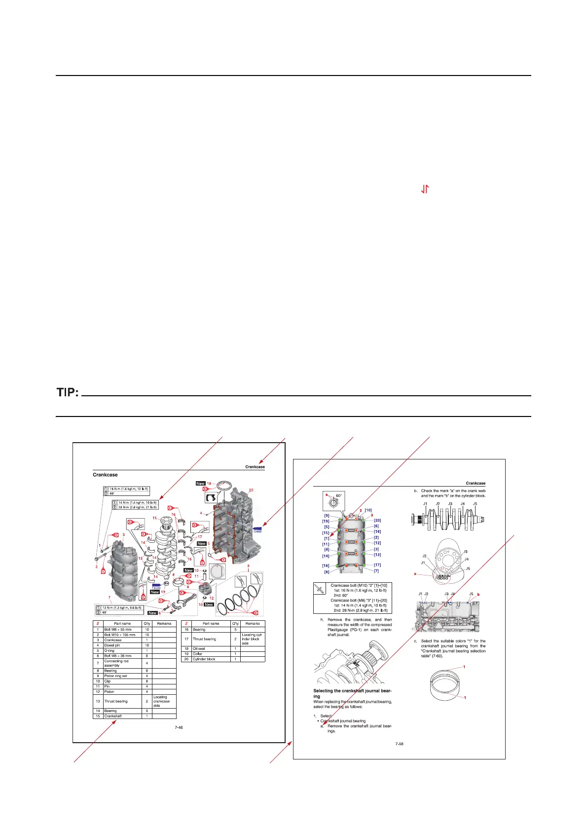
• Parts
are shown and detailed in an exploded diagram and are listed in the component list (see “1” in
the following figure for an example page).
• The component list consists of the removal or disassembly order numbers (“ ”), part names, quan-
tities, and remarks, which indicate the bolt and screw dimensions and other information (see “2” in th
e
following figure). For the installation or assembly procedure, reverse the order.
• Symbols are used to indicate important aspects
of a procedure, such as the grade of lubricant and
the lubrication points (see “3” in the following figure).
• Tightening torque
specifications are provided in the exploded diagrams (see “4” in the following fig-
ure), and in the related detailed instructions. Some torque specifications are listed in stages as torqu
e
figures or angles in degrees.
• Separate procedu
res and illustrations are used to explain the details of removal, checking, and instal-
lation where necessary (see “5” in the following figure
for an example page). Detailed explanations of
the procedures are expressed by using lower case letters such as a, b, c, …. (see “6” in the following
figure).
• Numbers enclosed in brackets are
used to indicate the removal or tightening order of bolts, screws,
and other parts (see “7” in the following figure).
For troubleshooting procedures, see Chapter 4, “Troubleshooting”.
1
6
7
2
34
5