Power unit assembly
7-9
r. Install the special service tool “3” to
the flywheel magneto, and then tight-
en the lifting eye bolts “2” to the speci-
fied torque.
s. Remove the special service tool “1”
from the flywheel magneto.
t. Hook a lifting harness onto the special
service
tool “3” and engine hanger “4”,
and then suspend the power unit “5”.
u. Remove the power unit mounting bolts
“6”,
“7”, and “8”, and then remove the
power unit “5” and dowel pins “9”.
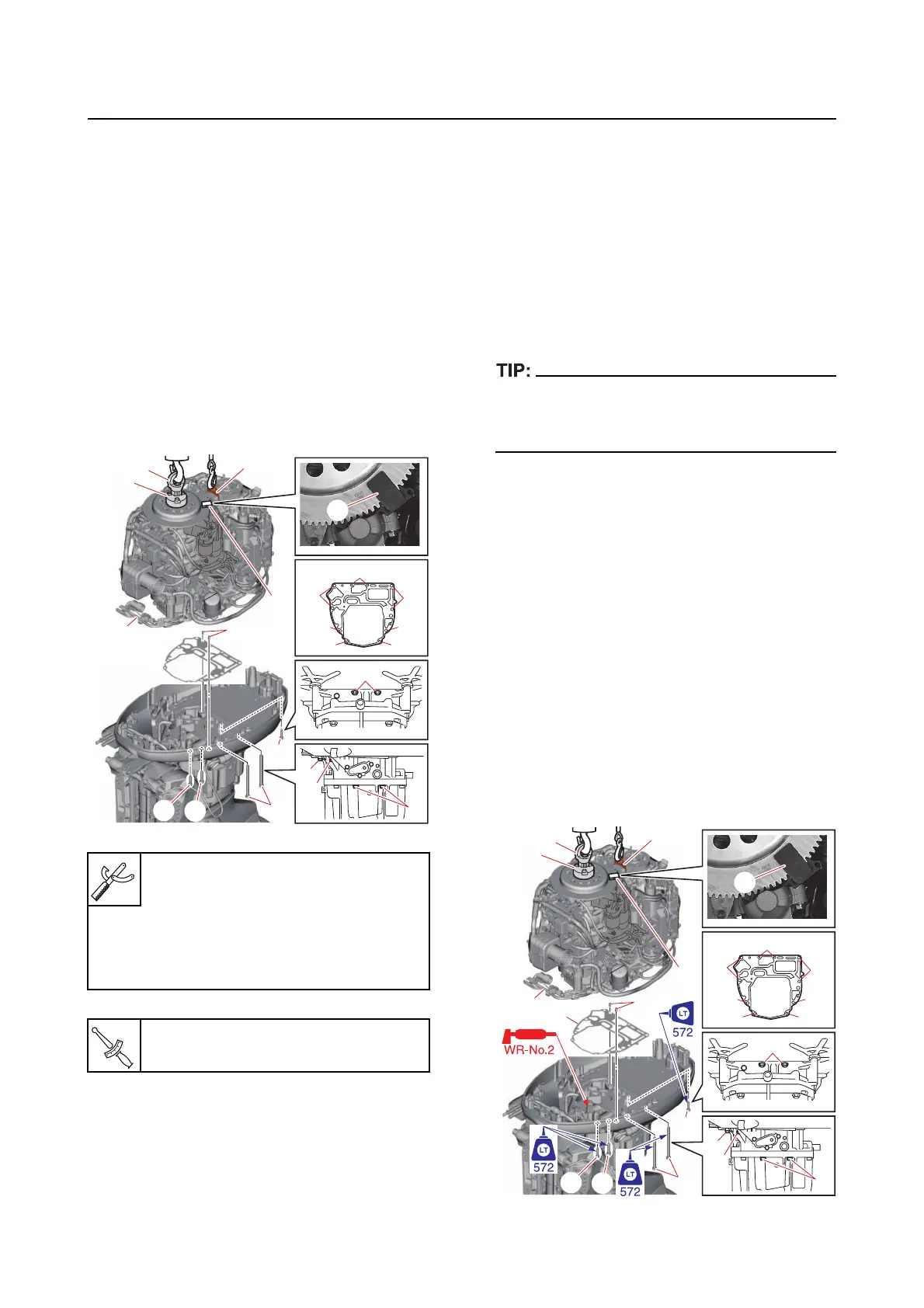
Installing the power unit
1. Install:
• Power unit assemb
ly
a. Clean the power unit mating surface,
and
then install the dowel pins “1” and
a new gasket “2”.
b. Attach the special service tool “3” to
prevent the flywheel magneto from
turning.
The special service tool “3” is installed to tight-
en the lifting eye bolts “4” to the specified
torque.
c. Install the special service tool “5” to
the flywheel magneto, and then tight-
en the lifting eye bolts “4” to the speci-
fied torque.
d. Remove the special service tool “3”
from the flywheel magneto.
e. Hook a lifting harness onto the special
service tool “5” a
nd engine hanger “6”,
and then suspend the power unit “7”.
f. Install the power unit “7”, and then
tighten the
power unit mounting bolts
“8”, “9”, and “10” to the specified
torque in the order [1], [2], and so on.
Flywheel stopper B “1”
90890-06686
Bolt hexagon with washer “2”
90890-06821
Lifting eye “3”
90890-06953
Lifting eye bolt “2”
36 N·m (3.6 kgf·m, 27 lb·ft)
5
6
10
10
99
88
10
8
4
8
3
7
9
8
10
8
9
8
3
1
2