Charging unit and component
5-27
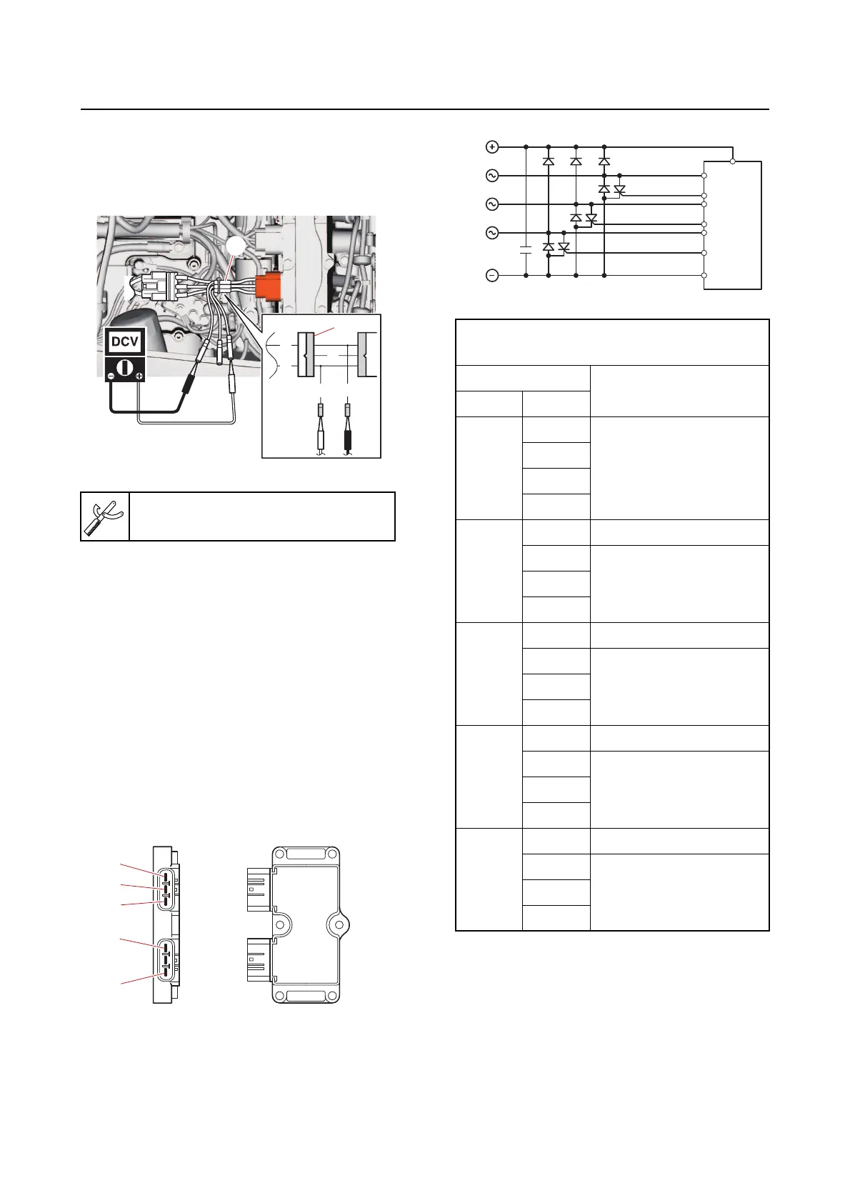
b. Connect the special service tool “1”,
and then measure the rectifier/regula-
tor output voltage at the specified en-
gine speed.
c. Disconnect the special service tool.
d. Connect the rectifier/regulator cou-
pler.
2. Check:
• Rectifier/regulator continuity
Out of specification Replace.
a. Disconnect the rectifier/regulator cou-
pler.
b. Set the digital circuit tester to the diode
mode, and then
check the rectifi-
er/regulator for continuity.
OL: Indicates an overload
c. Connect the rectifier/regulator cou-
pler.
Checking the hour meter
1. Disconnect:
• Hour meter coupler
Test harness QLW–3 “1”
90890-06922
R
R
B
R
B
1
1
c
d
e
b
a
Rectifier/regulator continuity
(testing diode mode)
Tester probe
Display value
(reference data)
(+) (–)
a
b
OL
c
d
e
b
a 0.5–0.6 V
c
0.5–0.6 Vd
e
c
a 0.5–0.6 V
b
OLd
e
d
a 0.5–0.6 V
b
OLc
e
e
a 0.5–0.6 V
b
OLc
d
a
c
d
e
b