Shimming
8-23
Measuring the forward gear backlash
and reverse gear backlash before dis-
assembly
1. Install:
• Lower unit (onto a repair stand)
2. Remove:
• Water pump assembly
• Outer plate cartridge
See “Water pump and shift rod” (8-3).
3. Measure:
• Forward gear backlash
• Reverse gear
backlash
Out of specification See “Selecting the
pinion shim (T3)” (8-28).
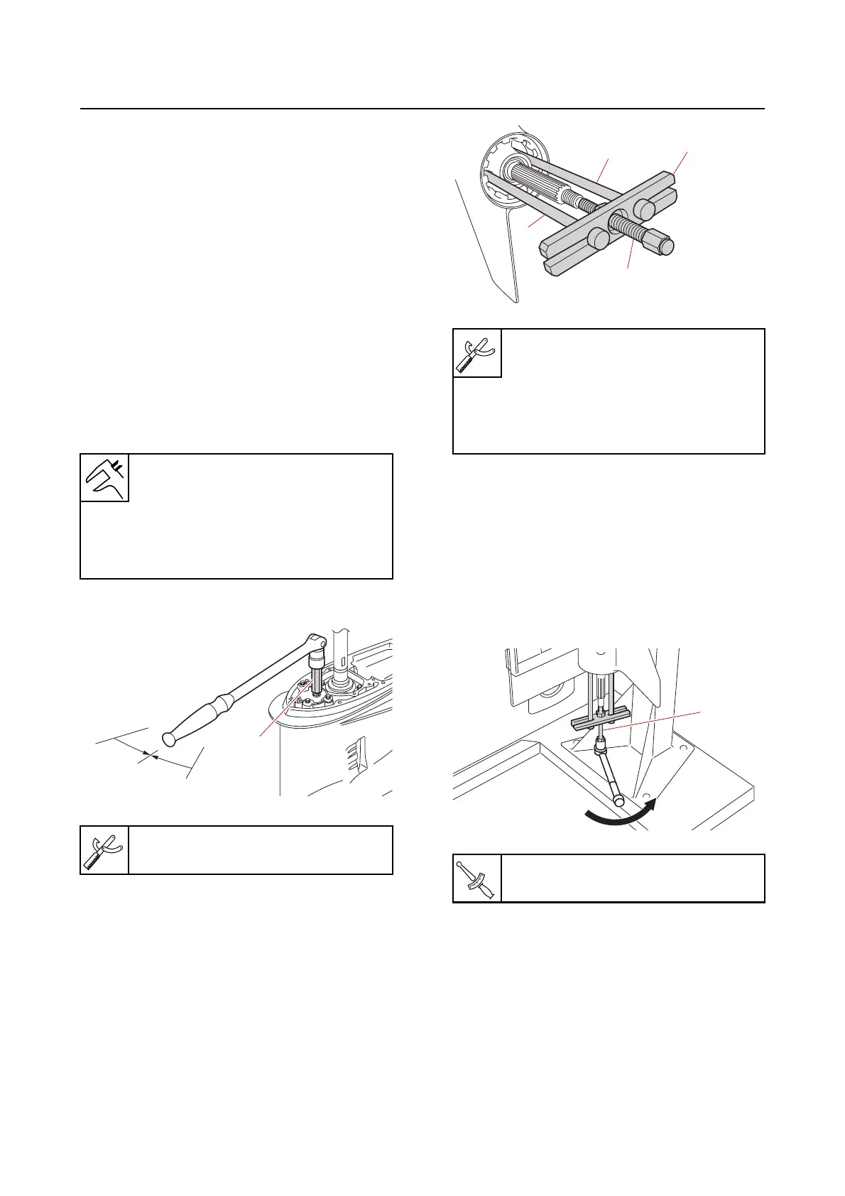
a. Set the gear shift to the N position.
b. Set up the special service tools “1”,
“2”,
and “3”, and then tighten the cen-
ter bolt “3” temporarily.
c. Turn the lower unit so that the propel-
ler shaft is pointing down.
d. Turn the drive shaft 10 turns or more
to seat the tapered roller
bearing.
e. While holding the drive shaft to pre-
vent it from turning, tighten the center
bolt “1” to the specified torque.
f. Place the lower unit in an upright posi-
tion.
Forward gear backlash
0.15–0.88 mm (0.0059–0.0346
in)
Reverse gear backlash
0.74–1.57 mm (0.0291–0.0618
in)
Shift rod socket “1”
90890-06681
Bearing housing puller claw L “1”
90890-06502
Stopper guide plate “2”
90890-06501
Center bolt “3”
90890-06504
Center bolt “1” (shimming)
5 N·m (0.5 kgf·m, 3.7 lb·ft)