PTT motor
9-33
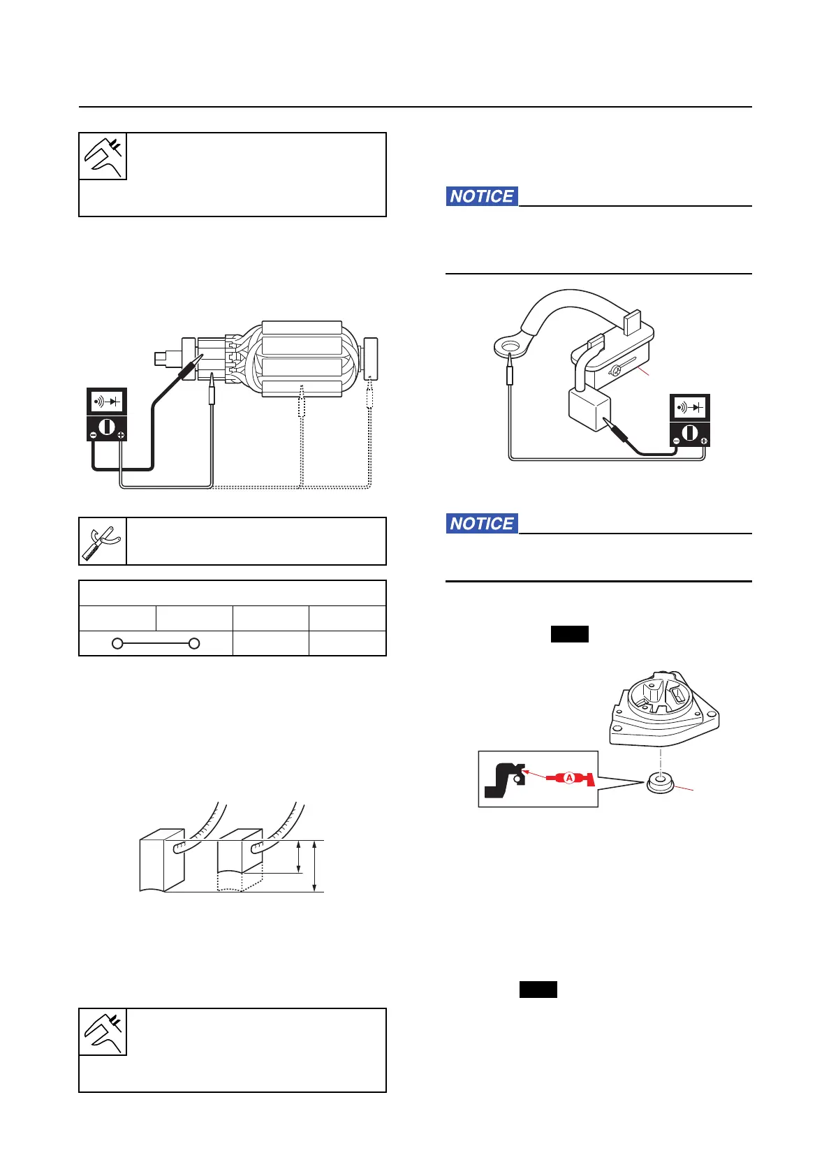
4. Check:
• Armature continuity
Out of specification Replace
the arma-
ture.
Checking the brush
1. Measure:
• Brush length
Below specification Replace
the brush.
2. Check:
• Circuit breaker continuity
No continuity Replace.
Do not touch the bimetal “1”. Otherwise,
the operation of the circuit breaker can be
affected.
Assembling the PTT motor
Do not apply grease or oil to the commuta-
tor of the armature.
1. Install:
• Oil seal
“1”
2. Install:
• Spring
• Circuit breaker
• Brush holder
• Brush
• PTT motor lead
• Screw
• O-ring (to the motor base assembly)
Standard commutator undercut
1.50 mm (0.0591 in)
Wear limit
1.00 mm (0.0394 in)
Digital circuit tester
90890-03243
Armature continuity
“a” “b” “c” “d”
a. Standard brush length
b. Wear limit
Standard brush length
10.00 mm (0.3937 in)
Wear limit
3.5 mm (0.14 in)