Cylinder block
7-44
2. Install:
• Oil seal “1” (into the oil pump hous-
ing “2”)
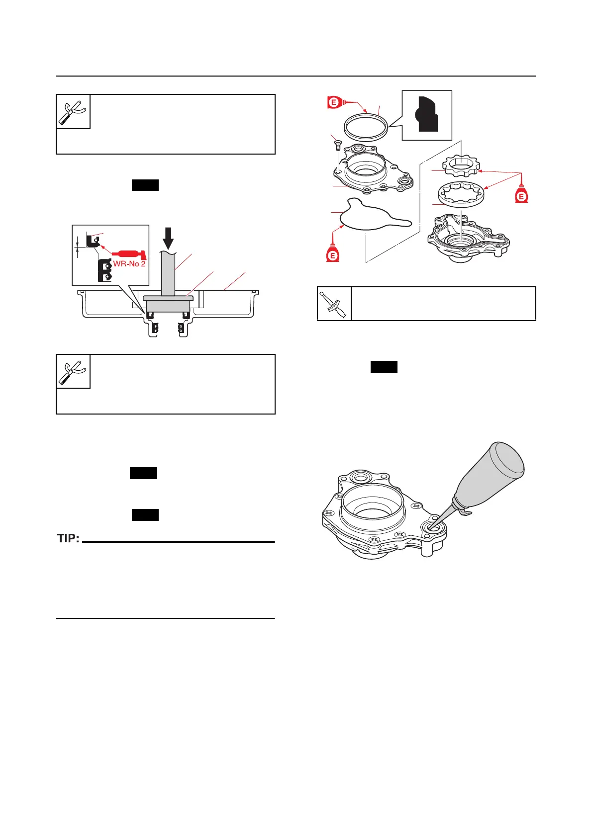
3. Install:
• Outer rotor
“1”
• Inner rotor “2”
• Gasket “3”
• Oil pump cover “4”
• Oil pum
p cover screw “5”
• Oil seal “6”
• Be sure to install the outer rotor “1” and inner
rotor “2” in the same direction as when they
were removed.
• Install a new oil seal “6” so that it is facing in
the proper direction.
Installing the oil pump assembly
1. Install:
• O-ring
• Oil pump assembly
• Oil pump assembly bolt
a. Fill the oil pump assembly with engine
oil through the oil passage.
Driver rod L3 “3”
90890-06652
Needle bearing attachment “4”
90890-06611
Driver rod L3 “3”
90890-06652
Needle bearing attachment “4”
90890-06607
1
2
3
4
Oil pump cover screw “5”
4.2 N·m (0.42 kgf·m, 3.1 lb·ft)
1
2
3
4
5
6