Crankcase
7-47
Disassembling the cylinder block
1. Remove:
• Connecting rod bolt “1”
• Connecting rod cap “2”
• Crankshaft pin bearing “3”
• Piston and connecting rod assembly
“4”
• To prevent mixing the piston and connecting
rod assemblies “4” and connecting rod caps
“2”, mark each with an identification number
“a” of the corresponding cylinder.
• Make sure to keep the parts in the order of re-
moval.
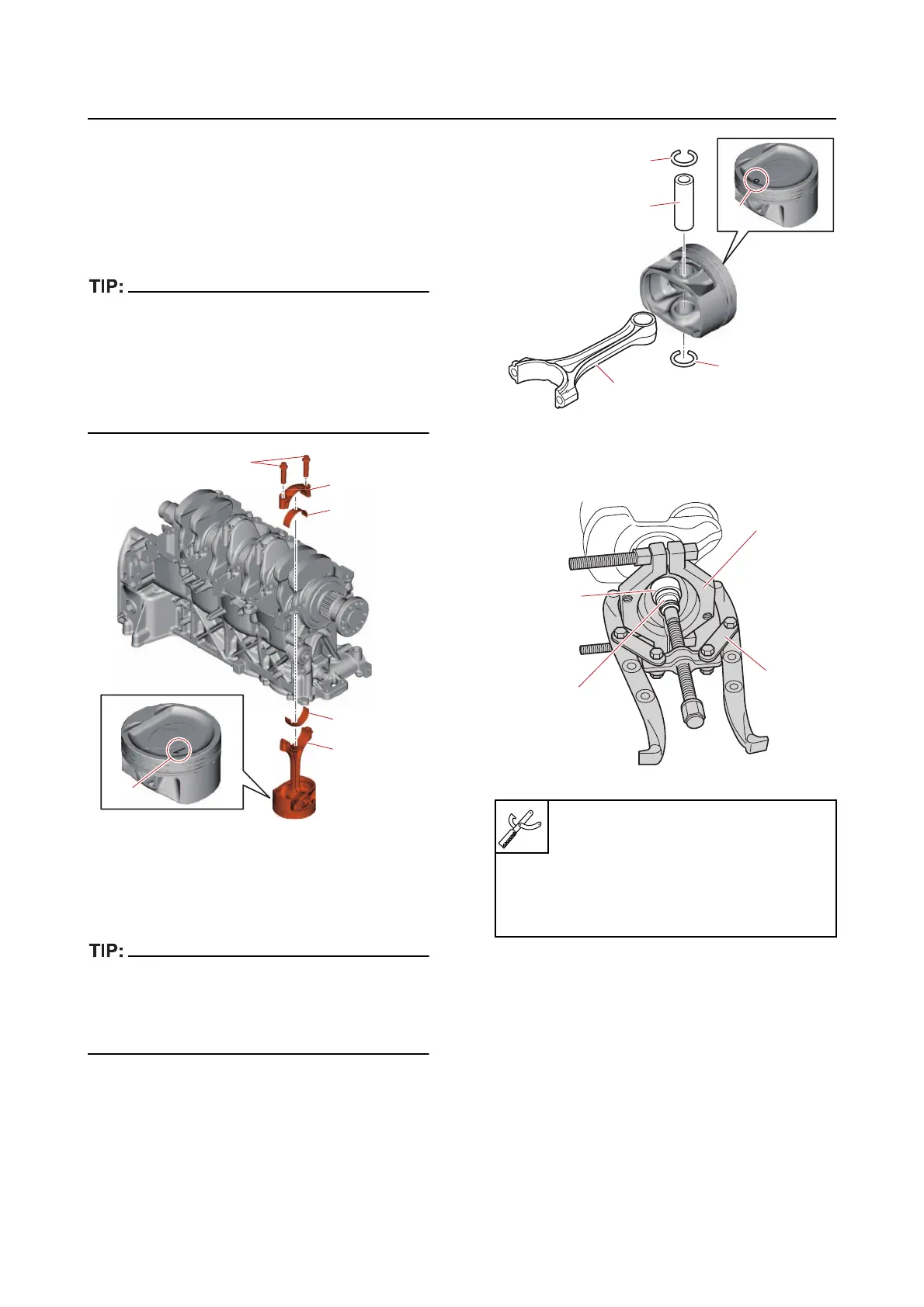
2. Remove:
• Cli
p “1”
• Piston pin “2”
• Connecting rod “3”
• Remove the piston pin from the side marked
with “a”.
• Make sure to keep the parts in the order of re-
moval.
3. Remove:
• Collar “1”
1
2
3
3
4
a
Bearing separator “2”
90890-06534
Gear puller “3”
90890-06540
Needle bearing attachment “4”
90890-06615
1
1
2
3
a
1
2
3
4