Optional equipment
3-10
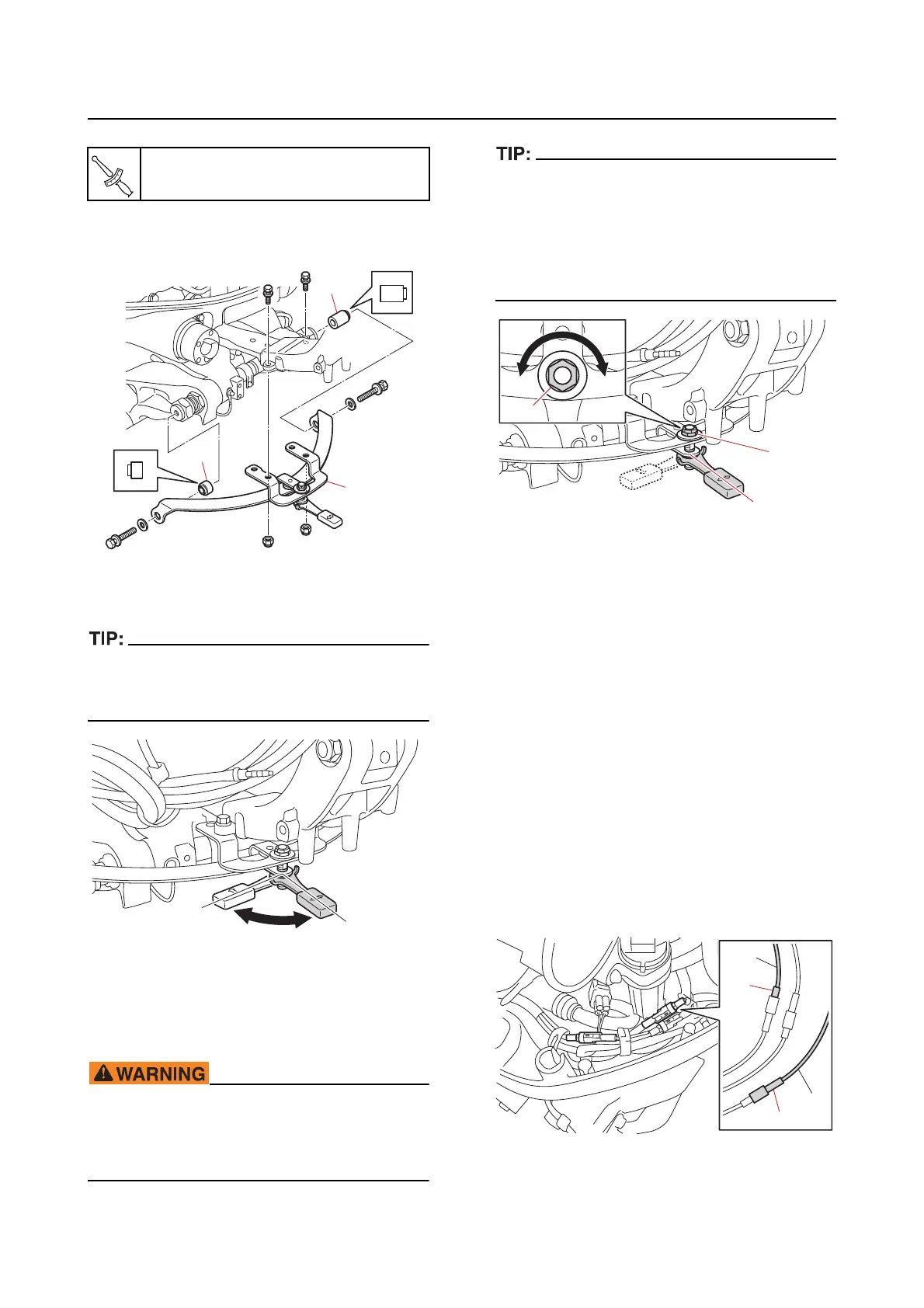
b. Install the friction plate assembly “1”
and collars “2” and “3”.
c. Check the friction plate assembly for
the amount of friction.
Make sure that the hoses, harnesses, leads,
and cables do not interfere with the friction
plate assembly.
d. Adjust the friction adjusting nut “1” so
that the steering operates properly.
Do not overtighten the friction adjuster. If
there is too much resistance, it could be dif
-
ficult to steer, which could result in an acci-
dent.
• Tighten or loosen the friction adjusting nut “1”
at the steering lock lever in the position “a”.
• To increase the friction, tighten the friction
adjusting nut “1” in direction “b”.
• To decrease the friction,
loosen the friction
adjusting nut “1” in direction “c”.
Optional equipment
Installing the tilt limiter (remote con-
trol model)
See TILT LIMITER INSTALLATION MANUAL
(68V-2819K-**-XX) for details of the compo-
nents. “XX” (2-digit suffix) varies depending on
the language.
Deactivating the tilt limiter (remote
control model)
To fully tilt the outboard motor up, deactivate
the tilt limiter according to the following proce-
dure.
1. Deactivate:
• Til
t limiter
a. Disconnect the tilt limiter couplers “a”
and “b
”.
Friction plate nut “1”
19.6 N·m (1.96 kgf·m, 14.5 lb·ft)
a. Increase the friction
b. Decrease the friction
a
b
a
c
b
1
1
S
L
a
b
b