Drive shaft and lower case
8-15
• Face the bearing identification mark “a” on
the needle bearing up.
• Mark the driver handle at the specified instal-
lation depth “b” with an identification mark “c”,
and
then install the needle bearing to the
specified installation depth. Make sure to
measure the depth on the driver handle from
the flange bottom of the special service tool
“2”.
3. Install:
• Water inlet cover (PORT
)
• Water inlet cover (ST
BD)
• Self-locking nut
• Water i
nlet cover screw
After installing the water inlet covers, make
sure that there is no rattling.
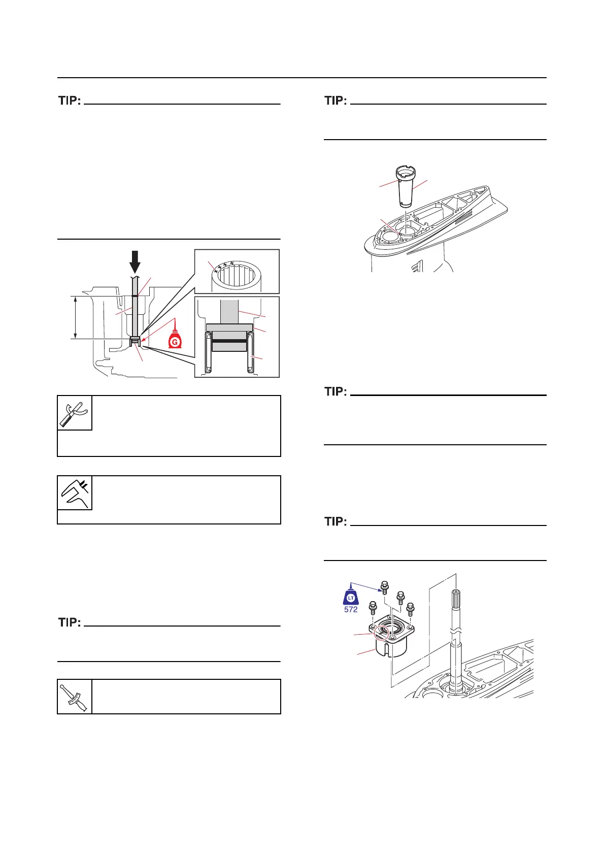
Installing the drive shaft
1. Install:
• Forward gear assembly
• Sle
eve “1”
Make sure that the protrusion “a” on the sleeve
“1” is aligned with the slot “b” in the lower case.
2. Install:
• Drive shaft
• Thrust bearing
• Pinion shim
• Pinion
• Pinion nut (temporarily tighten)
When installing the pinion, lift up the drive shaft
slightly and align the splines on the drive shaft
with the splines on the pinion.
3. Install:
• Drive shaft housing “1”
• Drive shaft housing bolt
Make sure to face the cutout “a” in the drive
shaft housing “1” forward.
4. Install:
• Cover
Driver rod L3 “2”
90890-06652
Needle bearing attachment “3”
90890-06609
Installation depth “b”
167.75–168.25 mm (6.604–6.624
in)
Water inlet cover screw
1.1 N·m (0.11 kgf·m, 0.81 lb·ft)
3
b
c
2
1
2
a
3
1
a
b