PTT gear pump
9-37
Disassembling the gear pump assem-
bly
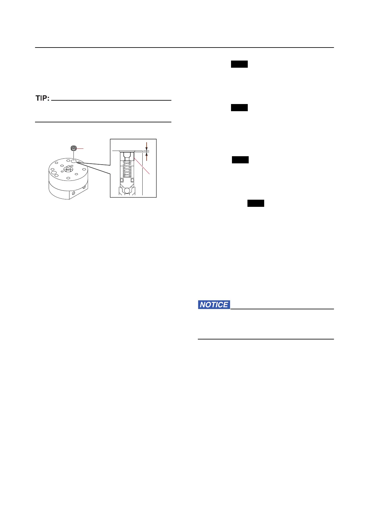
1. Remove:
• Valve lock screw “1”
Before removing the valve lock screw “1”, mea-
sure and write down the screw depth “a”.
Checking the gear pump
1. Check:
• Val
ve
• Bal
l
• Gear
Damaged/worn Replace.
2. Check:
• Filter
Clogged/damaged Rep
lace.
Assembling the gear pump housing
Lubricate the parts using recommended fluid
during assembly.
1. Install:
• O-ring (to the up-relief valve)
• Up-relief valve (to the
gear housing (upper
side))
• Main valve seal
• E-clip
• O-ring (to the down-main valve)
• Down-main valve
• Up-main valve
• Spring (to the down-main valve)
• Spring (to the up-main valve)
• Pin (to the gear housing (lower side))
• O-ring (to the gear housing (lower
side))
• Valve seat (to the gear housing (lower
side))
• Ball (to the valve seat)
• Valve seal (to the gear housing
(lower side))
• Down-relief
valve (to the gear housing
(lower side))
• Ball (to the gear housing (lower side))
• Pin (to the shaft)
• Drive gear (to the shaft)
• Driven gear (to the shaft)
• Shaft (to the gear housing (lower side))
• Gear housing
(upper side) (to the gear
housing (lower side))
Make sure that there is no gap between the
gear housings. If there is a gap, parts be-
tween them may not be installed properly.
2. Install:
• Spring “1”
• Valv
e lock screw “2”