PTT gear pump
9-38
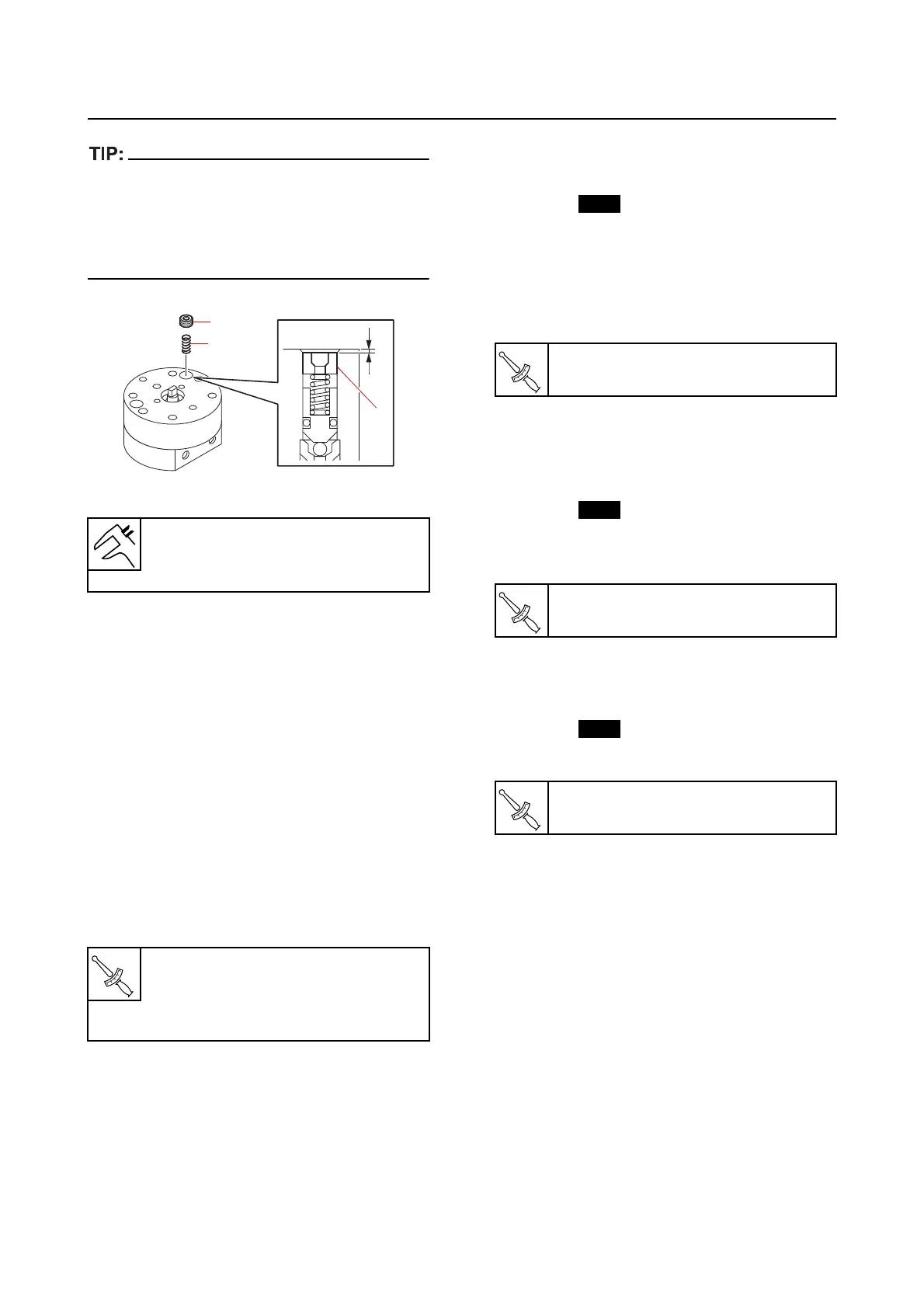
• Install the valve lock screw “2” to the position
“a” where it was measured before removing
the screw.
• When installing new parts, install them ac-
cording to the following reference data.
3. Install:
• Spring (to the gear housing (upper sid
e))
• Cap
• Gear pump housing
bolt (M3) (temporarily
tighten)
• Gear pump housing
bolt (M5) (temporarily
tighten)
4. Check:
• Gear pump movement
Not smooth Repeat from step (1).
5. Tighten:
• Gear pump housing bolt (M3)
• Gear pump housing bolt (M5)
6. Install:
• Ball (to the gear housing (lower side))
• Adapter
• O-ring
• Spring
• Ball (to the gear housing (lower side))
• Manual release plate
• Relief valve seat
• Relief valve seat bolt
7. Install:
• Plate (to the trim cylinder)
• Filter
• Filter
• O-ring
• Gear pump assembly
• Gear pump assembly bolt
8. Install:
• Shaft (to the gear pump assembly)
• Spring
• O-ring (to the trim cylinder)
• Manual valve
9. Install:
• Circlip
Installation depth “a” (reference da-
ta)
0.26 mm (0.0102 in)
Gear pump housing bolt (M3)
1.8 N·m (0.18 kgf·m, 1.3 lb·ft)
Gear pump housing bolt (M5)
5 N·m (0.5 kgf·m, 3.7 lb·ft)
Relief valve seat bolt
1.8 N·m (0.18 kgf·m, 1.3 lb·ft)
Gear pump assembly bolt
5 N·m (0.5 kgf·m, 3.7 lb·ft)
Manual valve
2.0 N·m (0.20 kgf·m, 1.5 lb·ft)