Tiller handle (tiller handle model)
3-9
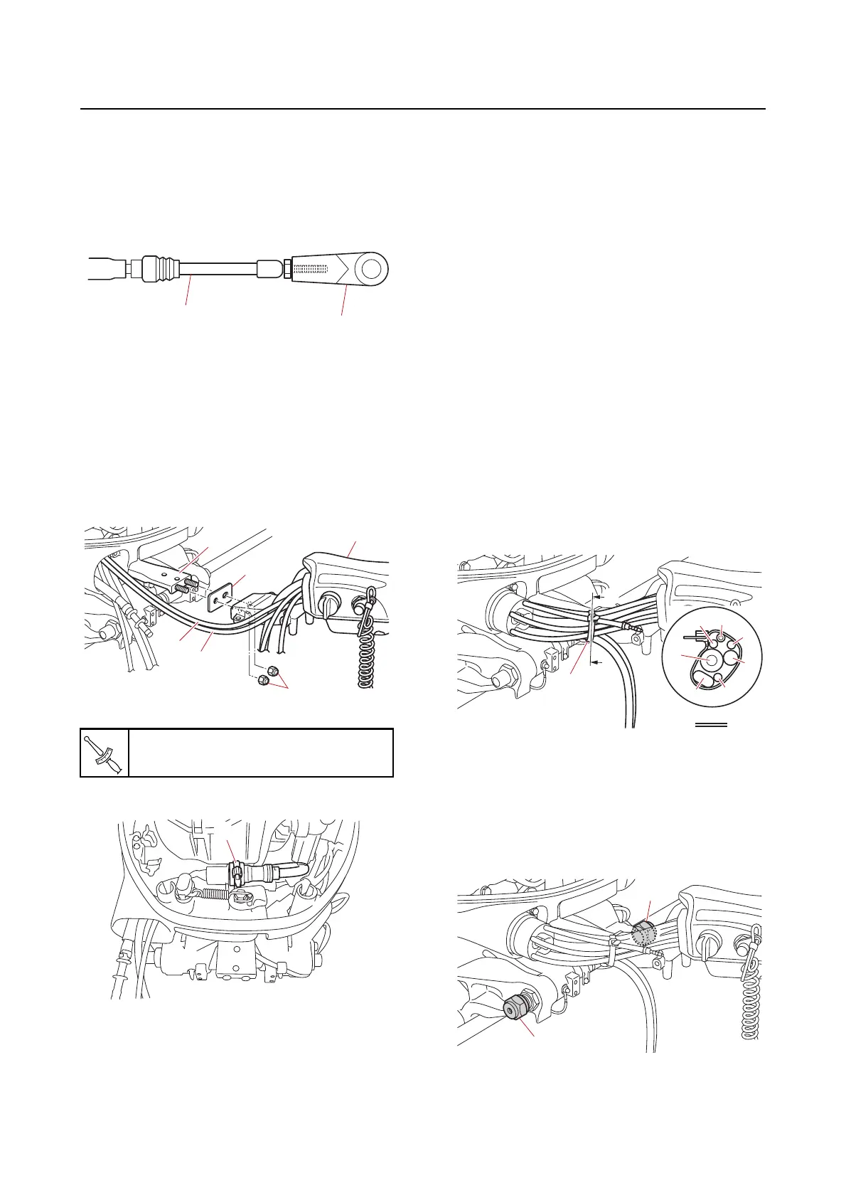
e. Install the shift cable joint “1” and throt-
tle cable joint “1” to the shift cable “2”
and throttle cable “2”.
f. Route the shift cable “1” and throttle
cable “2” through the bottom cowling.
g. Install the plate “3” and tiller handle as-
sembly “4” to the steering arm “5”, and
then
tighten the tiller handle nuts “6” to
the specified torque.
h. Release the holder “1”.
i. Install the gauge harness, main wire
harness, and battery cable. See “In-
stalling the conventional gauge
(6Y5/6Y7) harness” (3-7), “Installing
the main wire harness” (3-5), and “In-
stalling the battery cable” (3-5).
j. Install the shift cable. See steps (b)–
(h
) in “Installing the shift cable” (3-5).
k. Install the throttle cable. See steps
(b
)–(h) in “Installing the throttle cable”
(3-6).
l. Install the rigging grommet. See “In-
stalling the rigging grommet” (3-7).
m. Fasten the main wire harness “1”, bat-
tery cable “2”, gauge harness “3”, shift
cable “4”, throttle cable “5”, speedom-
eter hose “6”, and fuel hose “7” using
the plastic tie “8”.
Installing the friction plate
1. Install:
• Friction plate
a. Install the friction plate nuts “1” onto
both
through tube ends, and then
tighten them to the specified torque.
Tiller handle nut “6”
40 N·m (4.0 kgf·m, 30 lb·ft)
1
2
1
1



 To Next Page