Shimming
8-24
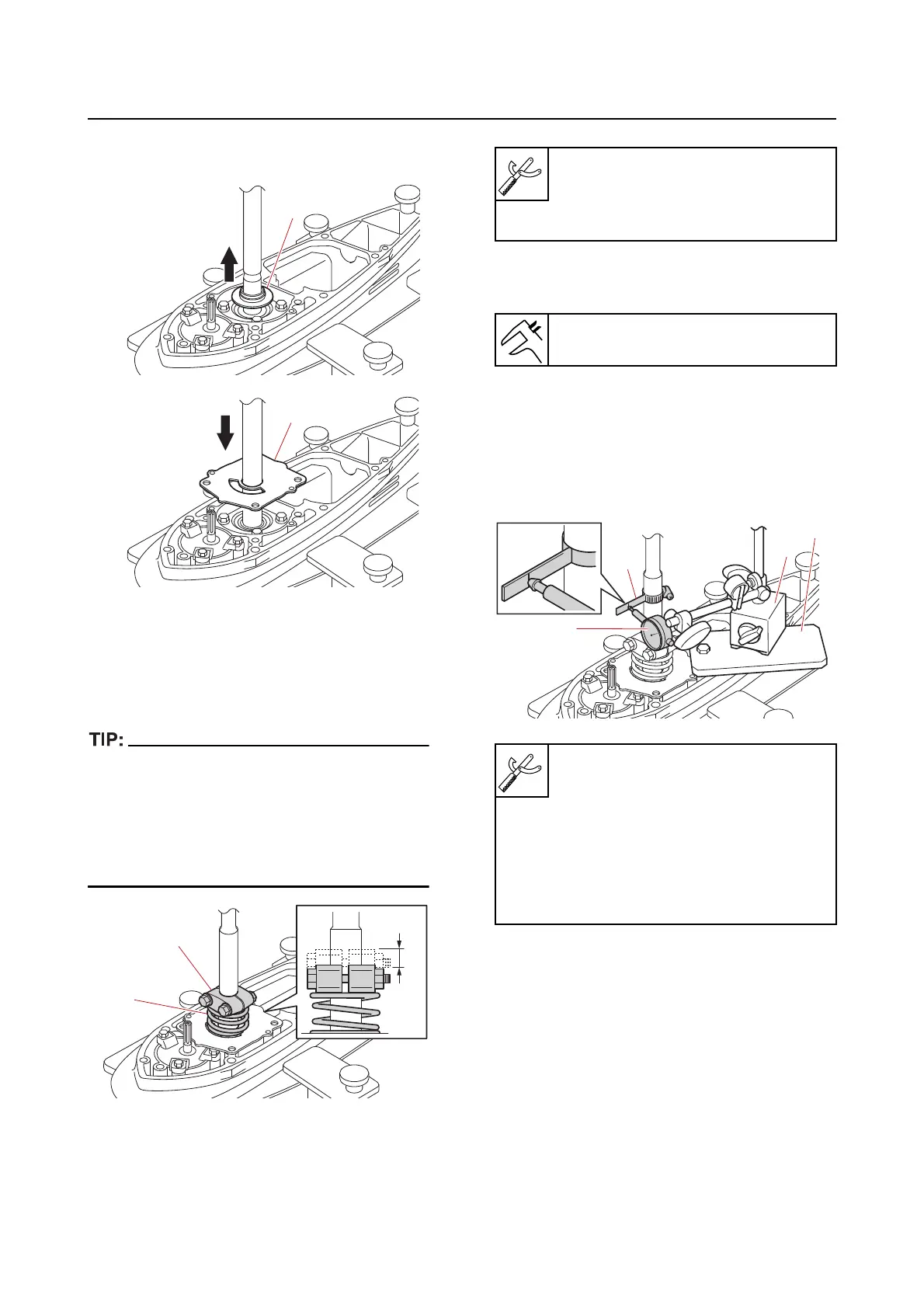
g. Remove the cover “1”, and then install
the outer plate cartridge “2”.
h. Set the spring “1” on the outer plate
cartridge, and
then install the handle
holder “2” so that the spring is com-
pressed to the specified setting height
“a”.
• After installing the handle holder, pull the
drive shaft upward to remove any free play.
• Do not press the spring more than 5.0 mm
(0.197 in). Otherwise, too much torque will be
required to turn the drive shaft, making it dif-
ficult to obtain correct measurements.
*1. Order from Yamaha Parts Distribu-
tion Center.
i. Install the special service tool “1” onto
the drive shaft at the lowest
possible
position where the shaft diameter is
22.4 mm (0.881 in), and then set up
the special service tools “2”, “3”, and
“4”.
j. Turn the drive shaft slowly clockwise
and counterclockwise, and then mea-
sure the backlash between where the
drive shaft stops
in each direction.
Spring “1”
90501-450A2 *1
Handle holder “2”
EU0-23814-30 (2 required) *1
Setting height
3.0–5.0 mm (0.118–0.197 in)
Backlash indicator “1”
90890-06706
Magnet base plate “2”
90890-07003
Dial gauge set “3”
90890-03238
Magnet base B “4”
90890-06844