Power unit assembly
7-8
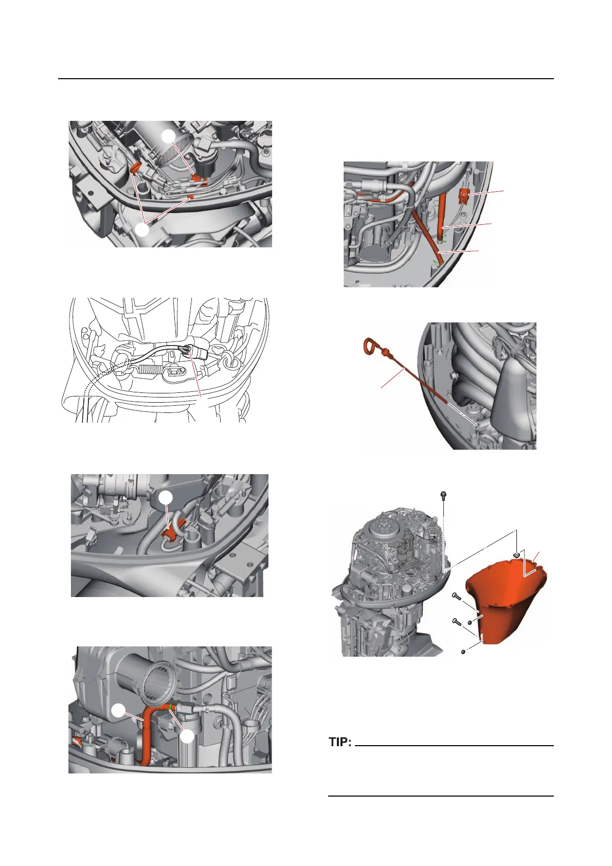
i. Disconnect the PTT switch coupler
“a”.
j. Disconnect the gauge harness cou-
pler “a”.
k. Disconnect the trim sensor coupler
“a”.
l. Remove the plastic tie “1”, and then
disconnect the fuel hose “2”.
m. Disconnect the vapor gas hose “1”
and cooling water pilot hose “2”.
n. Disconnect the shift position switch
coupler “a”.
o. Remove the dipstick “1”.
p. Remove the apron “1”.
q. Attach the special service tool “1” to
prevent the flywheel magneto from
turning.
The special service tool “1” is installed to tight-
en the lifting eye bolts “2” to the specified
torque.
a
1
a
2
1
2
1
a
1