Power unit assembly
7-10
g. Install the apron “1”, and then tighten
the apron screws “2” and “3” to the
specified torque.
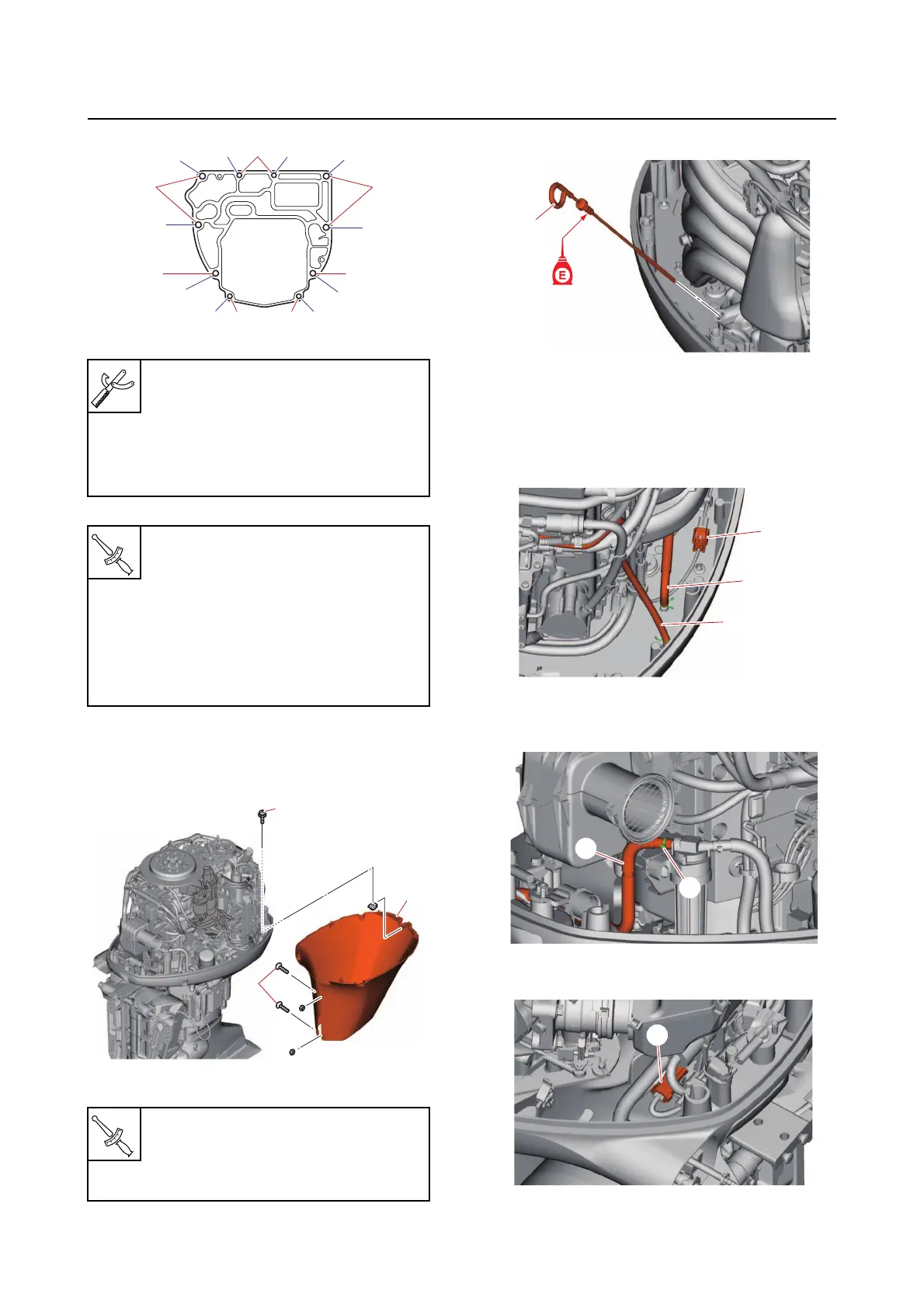
h. Install the dipstick “1”.
i. Connect the shift position switch cou-
pler “a”.
j. Connect the vapor gas hose “1” and
cooling water pilot hose “2”.
k. Connect the fuel hose “2”, and then
fasten it using a new plastic tie “1”.
l. Connect the trim sensor coupler “a”.
Flywheel stopper B “3”
90890-06686
Bolt hexagon with washer “4”
90890-06821
Lifting eye “5”
90890-06953
Lifting eye bolt “4”
36 N·m (3.6 kgf·m, 27 lb·ft)
Power unit mounting bolt (M8) “8”
20 N·m (2.0 kgf·m, 15 lb·ft)
Power unit mounting bolt (M10) “9”
and “1
0”
1st: 42 N·m (4.2 kgf·m, 31 lb·ft)
2nd: 42 N·m (4.2 kgf·m, 31 lb·ft)
Apron screw “2”
3.0 N·m (0.30 kgf·m, 2.2 lb·ft)
Apron screw “3”
3.9 N·m (0.39 kgf·m, 2.9 lb·ft)
[3]
[5]
[1]
8
8
[6], [8]
[4], [7]
[2]
10
[9]
9
[10]
[11]
[12]
10
9
8
1
2
1
a
2
1
a