Power unit assembly
7-11
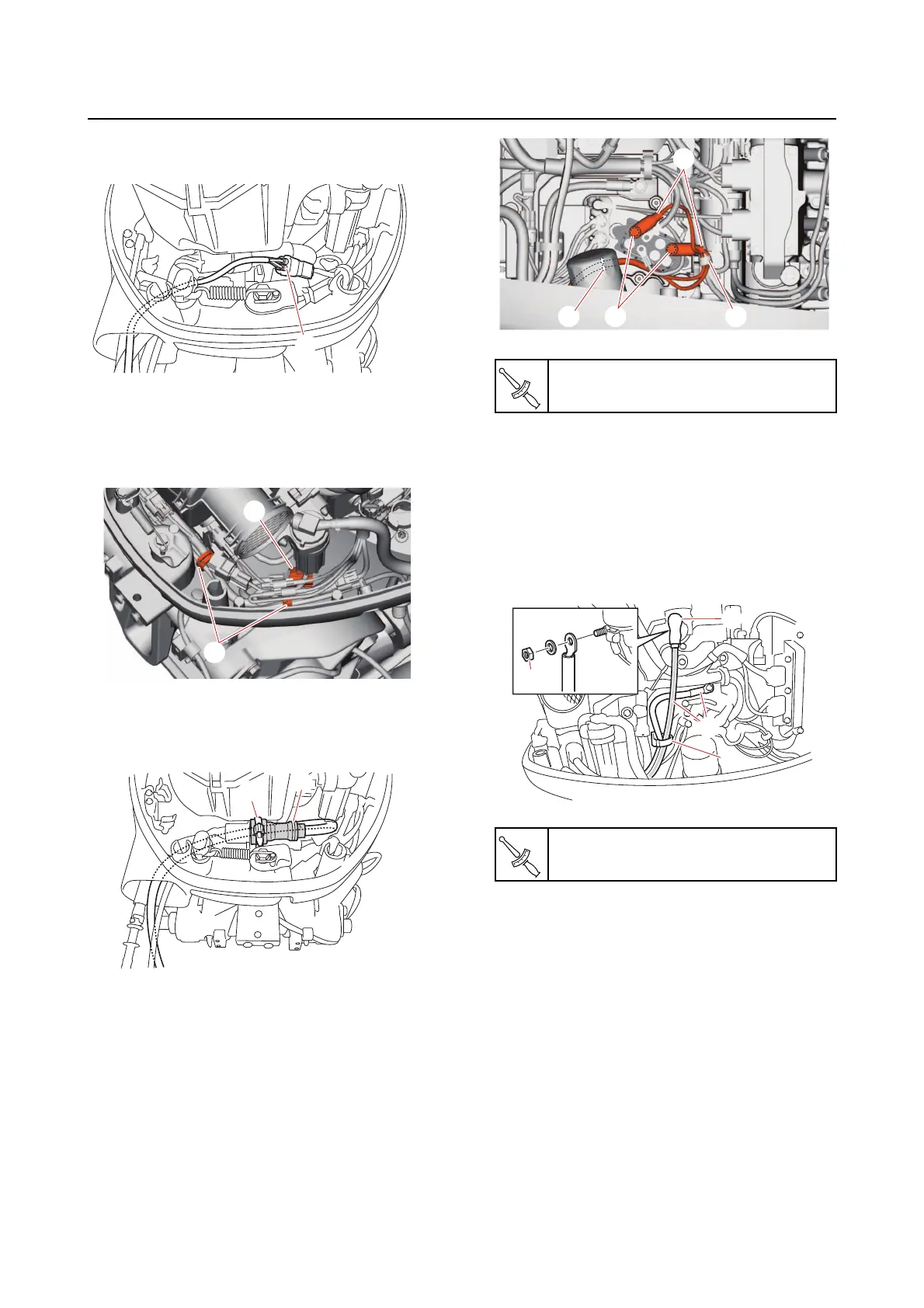
m. Connect the gauge harness coupler
“a”.
n. Connect the PTT switch coupler “a”.
o. Fasten the wire harness using the
clamps “1”.
p. Connect the main wire harness cou-
pler “a”, and then secure it using the
holder “1”.
q. Connect the PTT motor leads “1”, and
then tighten
the PTT motor lead bolts
“2” to the specified torque.
r. Fasten the PTT motor leads using the
clamps “3” and “4”.
s. Connect the battery cable “1”, and
then tighten the
positive battery cable
nut “2” to the specified torque.
t. Install the rubber cap “3”.
u. Fasten the battery cable “1” using the
holder “4”.
v. Install the shift cable. See “Installing
the shift cable” (3-5).
w. Install the throttle cable. See “Install-
ing the throttle cable” (3-6).
a
a
1
a
1
PTT motor lead bolt “2”
3.5 N·m (0.35 kgf·m, 2.6 lb·ft)
Positive battery cable nut “2”
9 N·m (0.9 kgf·m, 6.6 lb·ft)
2
1
4 3
1
4
2
3