Ignition unit and component
5-31
1. Check:
• Inta
ke air temperature sensor operation
Not operating Check the wire harness
for continuity.
a. Measure the ambient temperature.
b. Connect the YDIS to display “Intake
air temperature”.
c. Check that the difference between the
ambient temperature
and the dis-
played intake air temperature is within
± 5 C (±
9 F).
• Check the intake air temperature sensor
when the engine is cold.
• When checking the intake air temperature
sensor, remove the top cowling and do not
start the engine.
Checking the intake air pressure sen-
sor
The intake air pressure sensor is a component
of the intake air pressure/temperature sensor.
1. Measure:
• Inta
ke air pressure sensor input voltage
Out of specification Check the wire har-
ness for continuity.
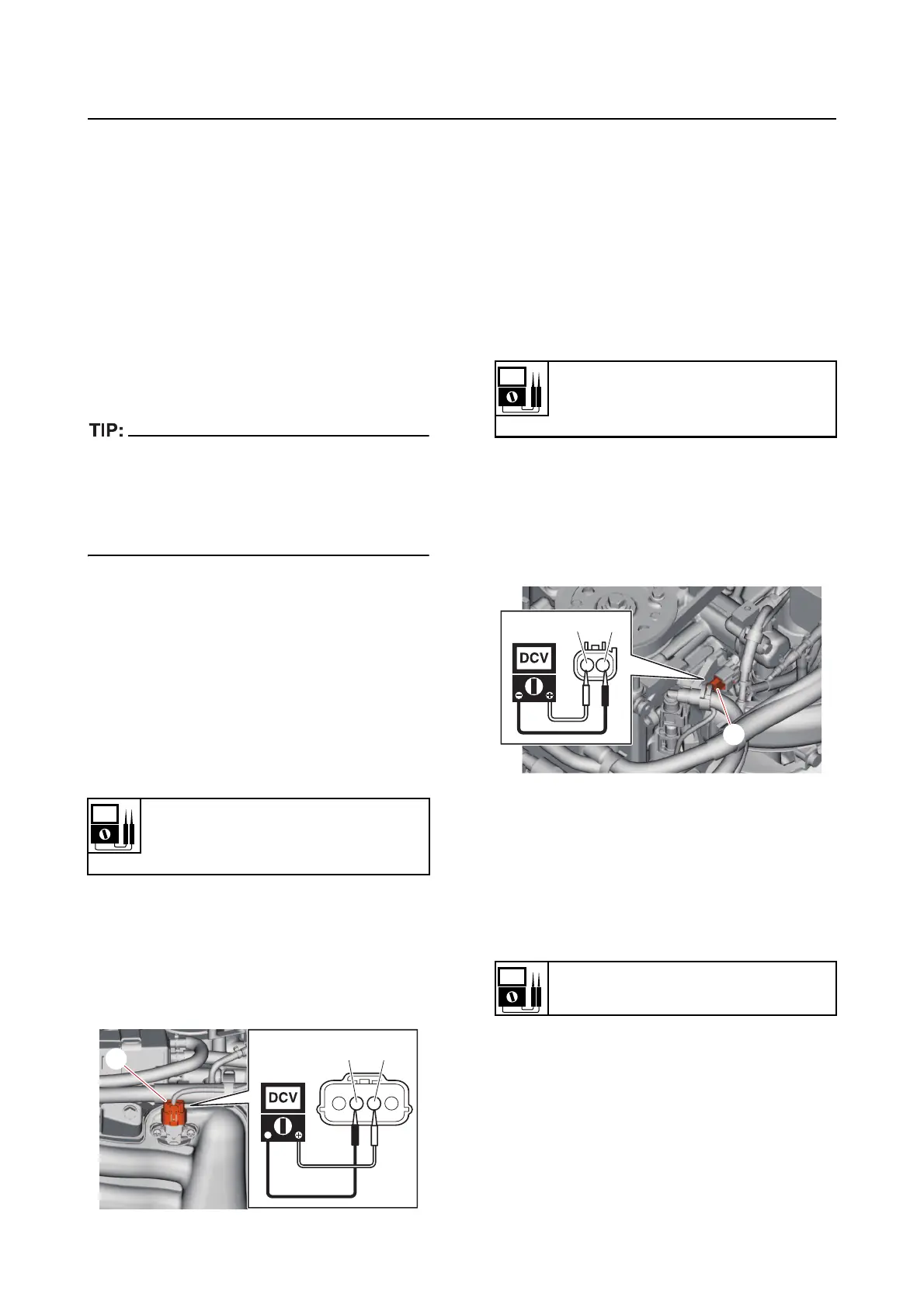
a. Disconnect the intake air pres-
sure/temperature sensor coupler “a”.
b. Turn the engine start switch to ON,
and then measu
re the input voltage at
the intake air pressure sensor coupler.
c. Turn the engine start switch to OFF.
d. Connect the intake air pressure/tem-
perature sensor coupler.
Checking the thermo sensor
1. Measure:
• Thermo
sensor input voltage
Out of specification Check the
wire har-
ness for continuity.
a. Disconnect the thermo sensor coupler
“a
”.
b. Turn the engine start switch to ON,
and then measure the input voltage at
the the
rmo sensor coupler.
c. Turn the engine start switch to OFF.
d. Connect the thermo sensor coupler.
2. Measure:
• Thermo sensor
resistance
Out of specification Replace.
a. Remove the thermo sensor.
b. Place the thermo sensor in a container
of water and heat the water slowly.
Input voltage
5 V
Orange (Or)–Black (B)
BOr
a
Input voltage
5 V
Black/White (B/W)–Black (B)
Resistance at 75 C (167 F)
0.360-0.383 k