Camshaft and valve
7-36
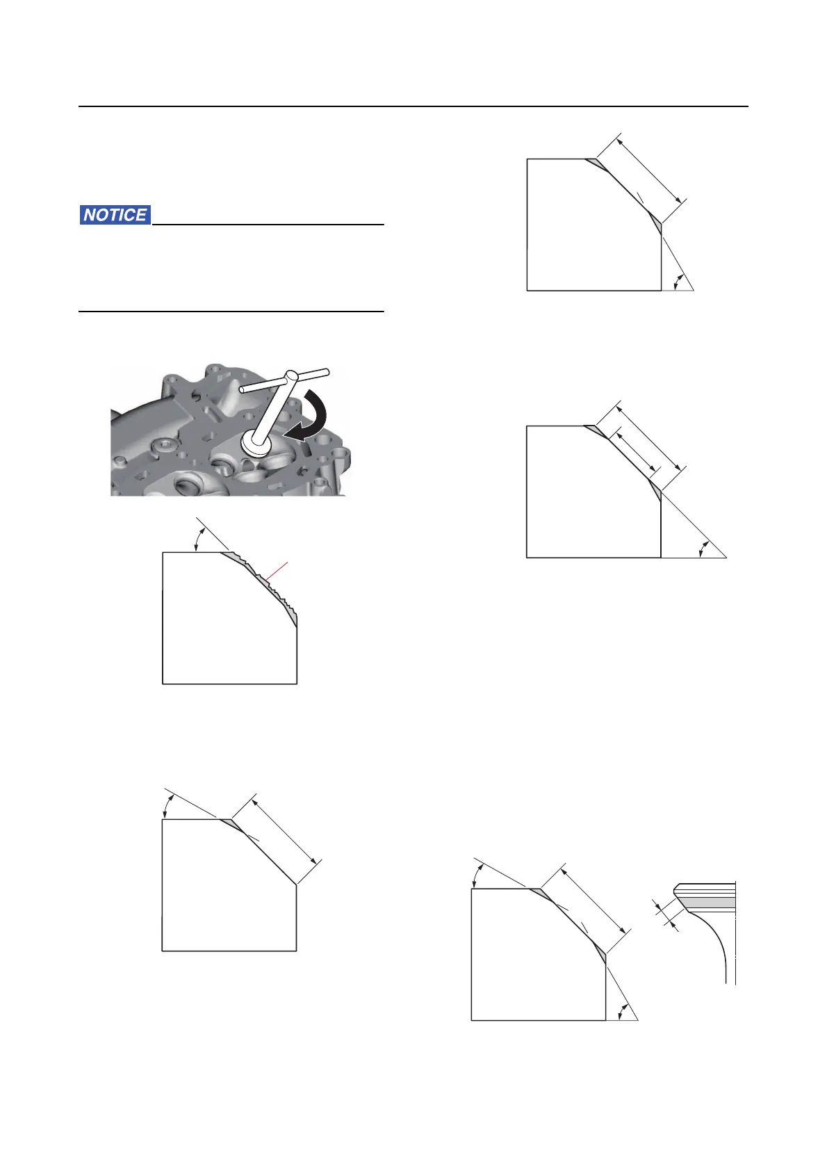
a. Cut the surface of the valve seat using
a 45 cutter by turning the cutter clock-
wise until the valve seat face has be-
come smooth.
Do not overcut the valve seat. To prevent
chatter marks, make sure to turn the cutter
evenly using a downward force of 40–50 N
(4.0–5.0 kgf, 8.8–11.0 lbf).
b. Adjust the top edge of the valve seat
contact width using a 30 cutter.
c. Adjust the bottom edge of the valve
seat contact
width using a 60 cutter.
d. Adjust the valve seat contact width to
specification using a 45 cutter.
e. Check the valve seat contact area of
the valve. See “Checking the valve
seat” (7-34).
• If the valve seat contact area is too
wide and situated in the center of the
valve face, cut the top edge of the
valve seat using a 30 cutter. Cut the
bottom edge using a 60 cutter to
center the area and set its width.
a. Slag or rough surface
a. Previous contact width
a
45°
30°
a
a. Previous contact width
a. Previous contact width
b. Specified contact width
a. Previous contact width
60°
a
45°
a
b
a
30°
60°