Drive shaft and lower case
8-19
3. Install:
• Dow
el pin
• Hose n
ipple
• Speedometer ho
se
• Hos
e joint
• Plastic tie
• Lower unit
• Lower case mounting bolt
4. Install:
• Tr
im tab
• Trim tab bolt
a. Install the trim tab “1” to its original po-
sition “a”, and then tighten the trim tab
bolt “2” to the specified torque.
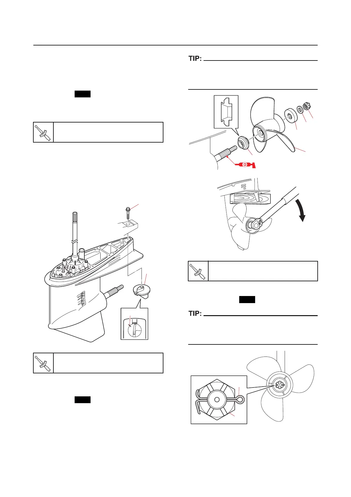
5. Install:
• Grommet
• Plastic tie
• Spacer “1”
• Propeller “2”
• Spacer “3”
• Washer “4”
• Propeller nut “5”
Place a block of wood between the anti-cavita-
tion plate and the propeller to prevent the pro-
peller from turning.
6. Install:
• Cotter pin “1”
If the slots in the propeller nut “2” are not
aligned with the cotter pin hole, tighten the pro
-
peller nut until they are aligned.
7. Fill:
• Gear oil
See the latest edition of the owner’s manual.
Lower case mounting bolt
40 N·m (4.0 kgf·m, 30 lb·ft)
Trim tab bolt “2”
42 N·m (4.2 kgf·m, 31 lb·ft)
Propeller nut “5”
54 N·m (5.4 kgf·m, 40 lb·ft)
1
2
3
4
5
1
2