Tiller handle (tiller handle model)
9-5
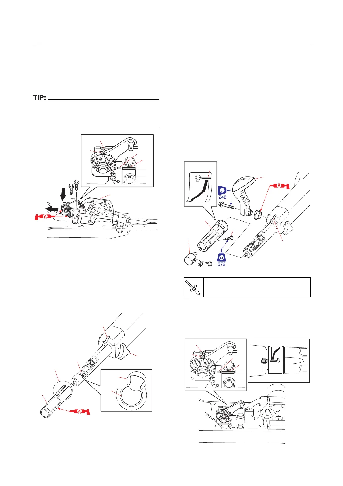
4. Install:
• Control link assembly
a. Align the marks “a” and “b”, and align
the cutouts “c” and “d”, and then install
the control link assemb
ly “1”.
Route the neutral switch lead under the control
link assembly “1”. See
“Tiller handle (tiller han-
dle model)” (5-11).
5. Install:
• Bus
hing
a. Face the section “a” of the plate “1” to-
ward the throttle friction adjuster “2”.
b. Align the slot “b” in the bushing “3” with
the protrusion
“c” on the tiller handle,
and then install the bushing “3”.
6. Install:
• Throttle grip
• Throttle grip screw
a. Align the mark “a” on the throttle grip
“1
” with the protrusion “b” on the tiller
handle, and then install the throttle
grip “1”.
b. Tighten the throttle grip screw “2” to
the specified torque.
7. Install:
• PTT switch “3”
• Shift lever
“4”
8. Check:
• Smooth operation of the throttle grip
• Alignment of the
marks “a” and “b”
• Alignment of the
cutouts “c” and “d”
Throttle grip screw “2”
1.6 N·m (0.16 kgf·m, 1.2 lb·ft)