Electronic control system
2-3
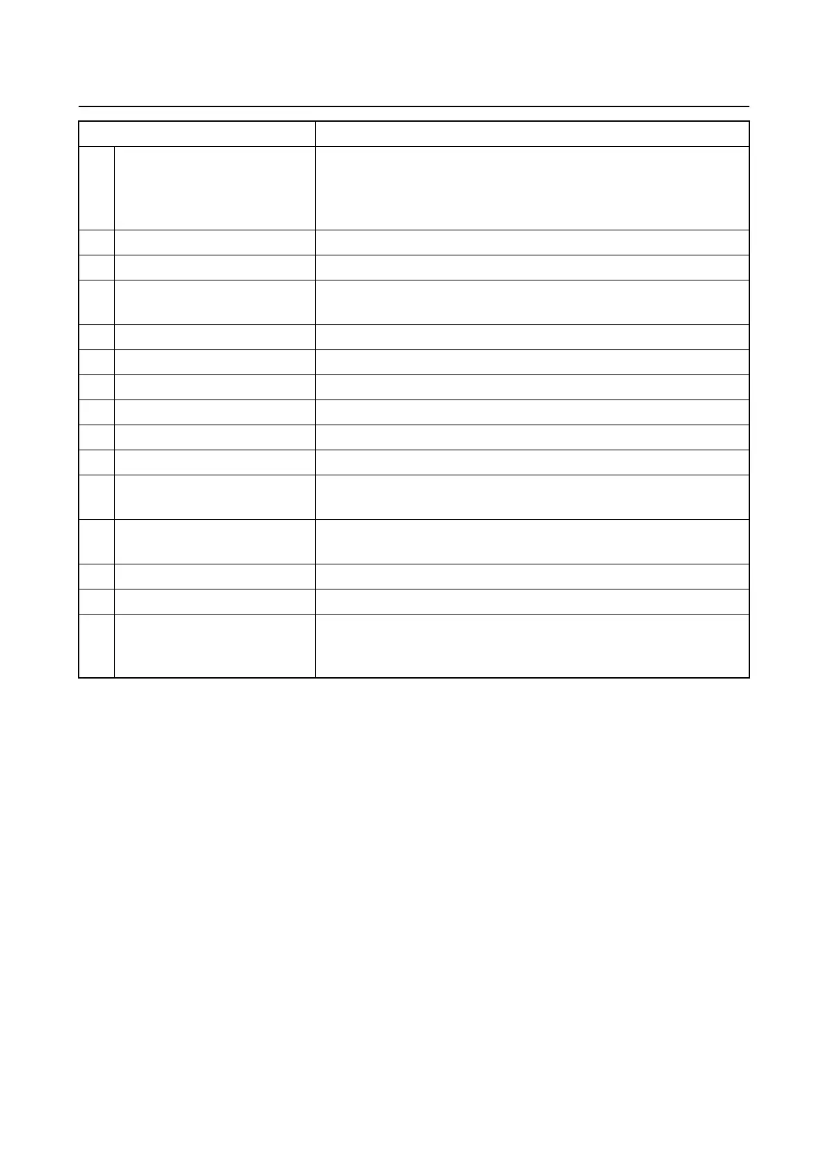
Part name Function
1 Engine ECM
Determines the engine operating conditions based on the input
signals from the
sensors which are installed at various loca-
tions on the engine, and transmits control signals to each actu-
ator.
2 Pulser coil Detects the engine speed and crankshaft angle.
3 TPS Detects the throttle valve opening angle.
4
Intake air pressure/temper-
ature sensor
Detects the intake air temperature and pressure.
5 Oil pressure switch Detects oil pressure decrease.
6 Thermo sensor Detects water temperature.
7 Shift position switch Detects the neutral position.
8 Fuel injector Injects fuel.
9 Ignition coil Produces high voltage to ignite a spark plug.
10 High-pressure fuel pump Pressurizes and feeds the fuel to the fuel rails for injection.
11 ISC valve
Adjusts the intake air distribution to the engine when the throt-
tle valve is fully closed.
12 Vapor shut-off valve
Controls the amount of vapor gas that is sent from the VST to
the intak
e system to be reburned.
13 Knock sensor Detects engine knocking.
14 Water detection switch Detects water accumulated in the fuel filter.
15 Fuse box
Contains the main relay, high-pressure fuel pump relay, starter
rela
y, and various fuses, and controls the power supply for the
electrical components of the outboard motor.