PTT unit
9-26
g. Reverse the connection between the
battery jumper leads and the PTT mo-
tor lead “1” to fully extend the trim and
tilt ram.
If the trim and tilt ram does not move up easily,
pull on the trim and tilt ram to assist operation.
h. Repeat steps (f) and (g) to fully extend
and retract the trim and tilt ram 4 or 5
times.
i. Fully extend the trim and tilt ram.
j. Remove the reservoir cap, and then
check the fluid level.
If the fluid is below the proper level, add the
recommended PTT fluid. Repeat steps (c)–(i)
until the fluid is at the proper level.
k. Install a new O-ring and the reservoir
cap, and then tighten the reservoir cap
to the specified torque.
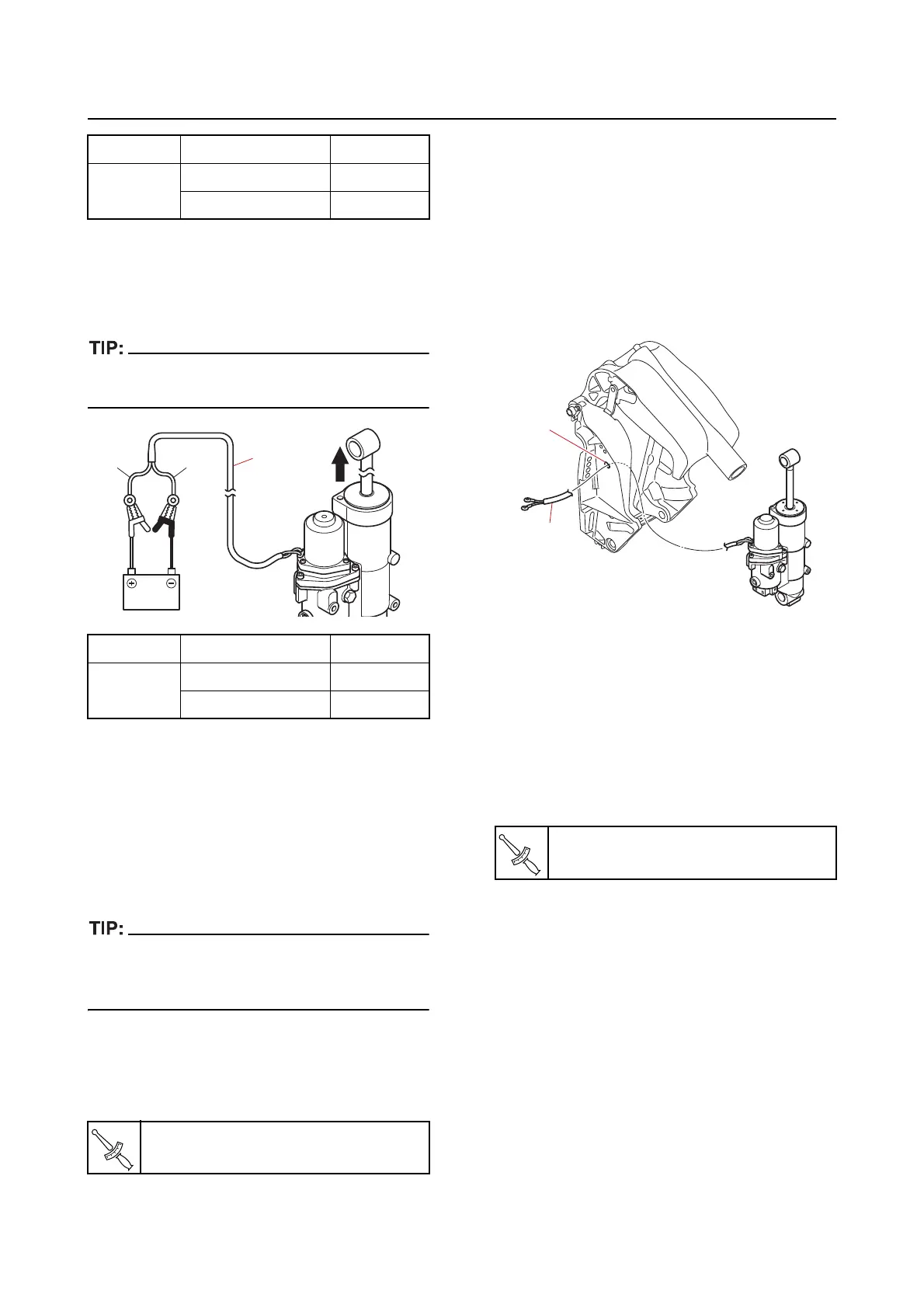
Installing the PTT unit
1. Install:
• Bushing (upper side)
2. Route:
• PTT motor lead
a. Route the PTT motor lead “1” through
the
hole “a” in the clamp bracket
(PORT).
3. Install:
• PTT unit
• Shaft (upper side)
• Circlip
• Bushing (lower side
)
• Shaft (lower side)
• Washer
• Shaft bolt
4. Install:
• Ground lead
• Ground lead bolt
Ram PTT motor lead Battery
Retract
Green (G) (+)
Blue (L) (–)
Ram PTT motor lead Battery
Extend
Blue (L) (+)
Green (G) (–)
Reservoir cap
7 N·m (0.7 kgf·m, 5.2 lb·ft)
L
G
1
Shaft bolt
54 N·m (5.4 kgf·m, 40 lb·ft)
1
a