Clamp bracket and swivel bracket
9-30
8. Install:
• Trim sensor ca
m
• Trim sensor ca
m screw
• Plastic tie
9. Inject:
• Grease
a. Inject grease into the grease nipples
until grease comes out from the bush-
ings “a”.
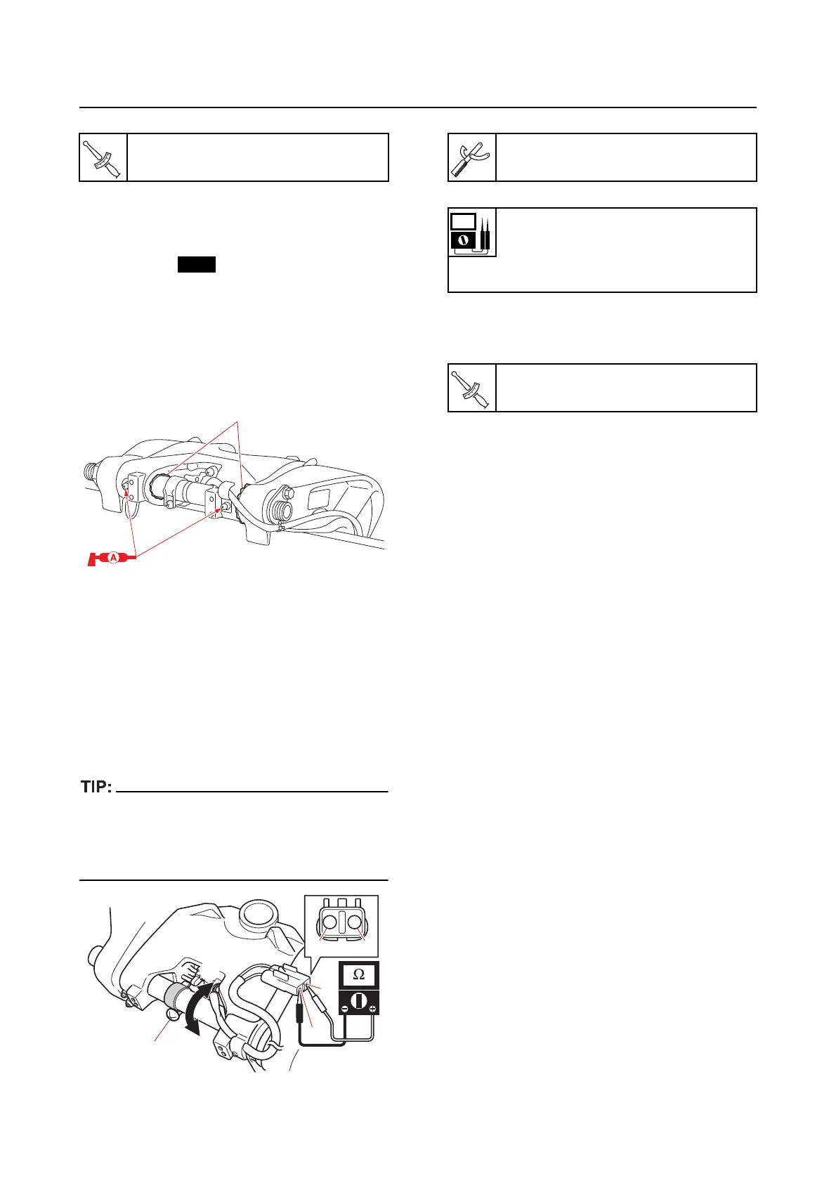
Adjusting the trim sensor cam
1. Adjust:
• Trim sensor se
tting resistance
a. Fully tilt the swivel bracket down.
b. Loosen the trim sensor cam screw “1”.
c. Measure the trim sensor setting resis-
tance. Adjust if out of specification.
• To decrease the resistance, turn the trim
sensor cam in direction “a”.
• To increase the resistance, turn the trim sen-
sor cam in direction “b”.
d. Tighten the trim sensor cam screw to
the specified torque.
2. Check:
• Trim sensor setting resistance
Out of specification Repeat
from step
(1).
Grease nipple
3.0 N·m (0.30 kgf·m, 2.2 lb·ft)
a
1
c
c
d
d
a
b
Digital circuit tester
90890-03243
Trim sensor
Setting resistance
9–11
Terminal “c”–Terminal “d”
Trim sensor cam screw
2.0 N·m (0.20 kgf·m, 1.5 lb·ft)