B.2 Parameter Table
358 YASKAWA TM.V1000.01 V1000 Drive Installation & Start-Up Manual (Preliminary 01-19-07)
E1-08
Mid Output
Frequency
Voltage (VC)
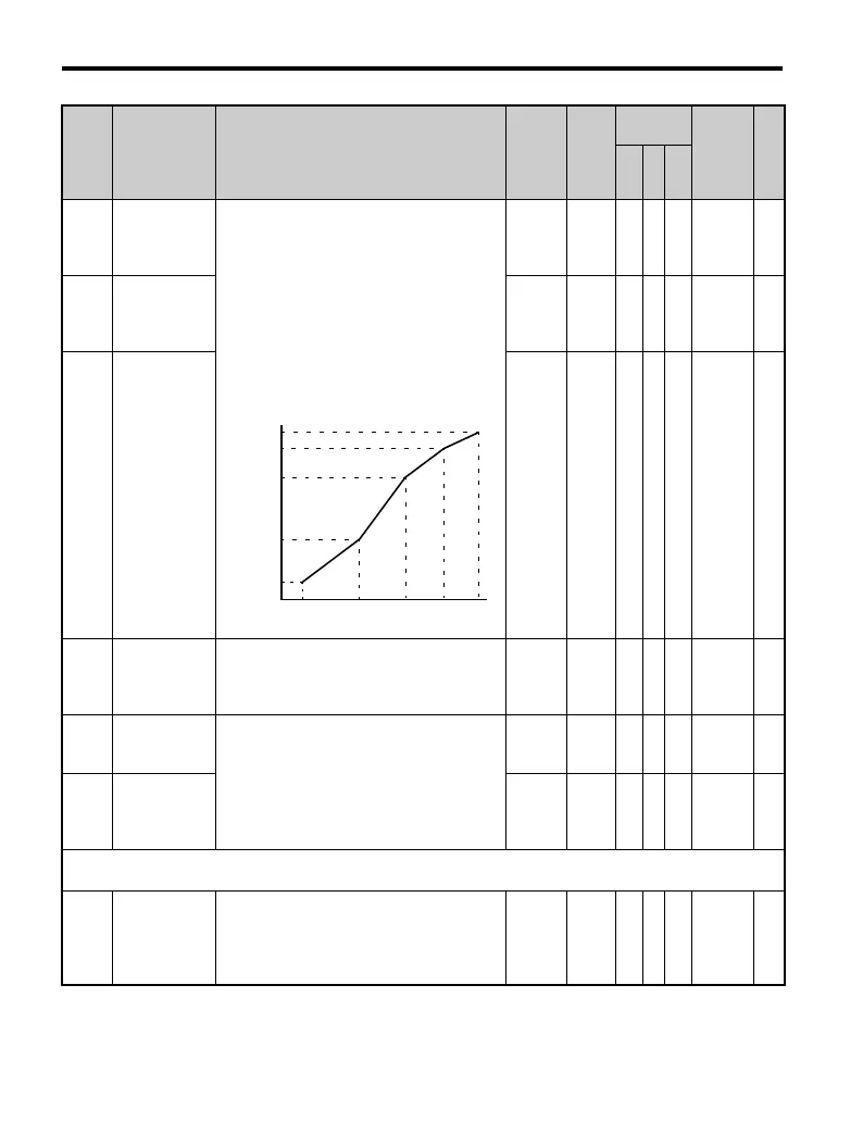
E1-08 to E1-13 parameters are only
applicable when V/f Pattern Selection is set to
Custom (E1-03 = F or FF). To set linear V/f
characteristics, set the same values for E1-07
and E1-09. In this case, the setting for E1-08
will be disregarded. Ensure that the four
frequencies are set according to these rules or
OPE10 fault will occur:
E1-04(FMAX) ≥ E1-06(FA)
> E1-07 (FB) ≥ E1-09 (FMIN)
0.0 to
255.0
<24>
15.0 V
<2>
<35> <
36>
A A A 307 —
E1-09
Minimum
Output
Frequency
(FMIN)
0.0 to
400.0
<10>
1.5 Hz
<2>
SSS 308 144
E1-10
Minimum
Output
Frequency
Voltage
(VMIN)
0.0 to
255.0
<24>
9.0 V
<2>
A A A 309 —
E1-11
<26>
Mid Output
Frequency 2
Set only when fine tuning the V/f pattern
within the constant power (HP) range above
base speed. This parameter does not typically
require adjustment.
0.0 to
400.0
<10>
0.0 Hz A A A 30A —
E1-12
<26>
Mid Output
Frequency
Voltage 2
Set only when the V/f pattern is finely
adjusted in the constant power (HP) area
above base speed. This parameter does not
typically require adjustment.
0.0 to
255.0
<24>
0.0 V A A A 30B —
E1-13
Base Voltage
(VBASE)
0.0 to
255.0
<24>
<28>
0.0 V A S S 30C 117
E2: Motor Parameters
Use E2 parameters to set motor-related data.
E2-01
Motor Rated
Current
Sets the motor nameplate full load current in
amperes (A). This value is automatically set
during Auto-Tuning.
10 to
200% of
drive
rated
current
<27> SS− 30E 147
No. Name Description Range Def.
Control
Mode
Addr.
Hex
Pg.
V/f
O
L
V
P
M
VACrms Out(V)
Frequency (Hz)
E1-09 E1-07 E1-06 E1-11 E1-04
E1-05
E1-12
E1-13
E1-08
E1-10

 Loading...


