2 Installation and Commissioning, IRC5
2.9.7. Installation of Euromap and SPI
3HAC021313-001 Revision: K126
© Copyright 2004-2008 ABB. All rights reserved.
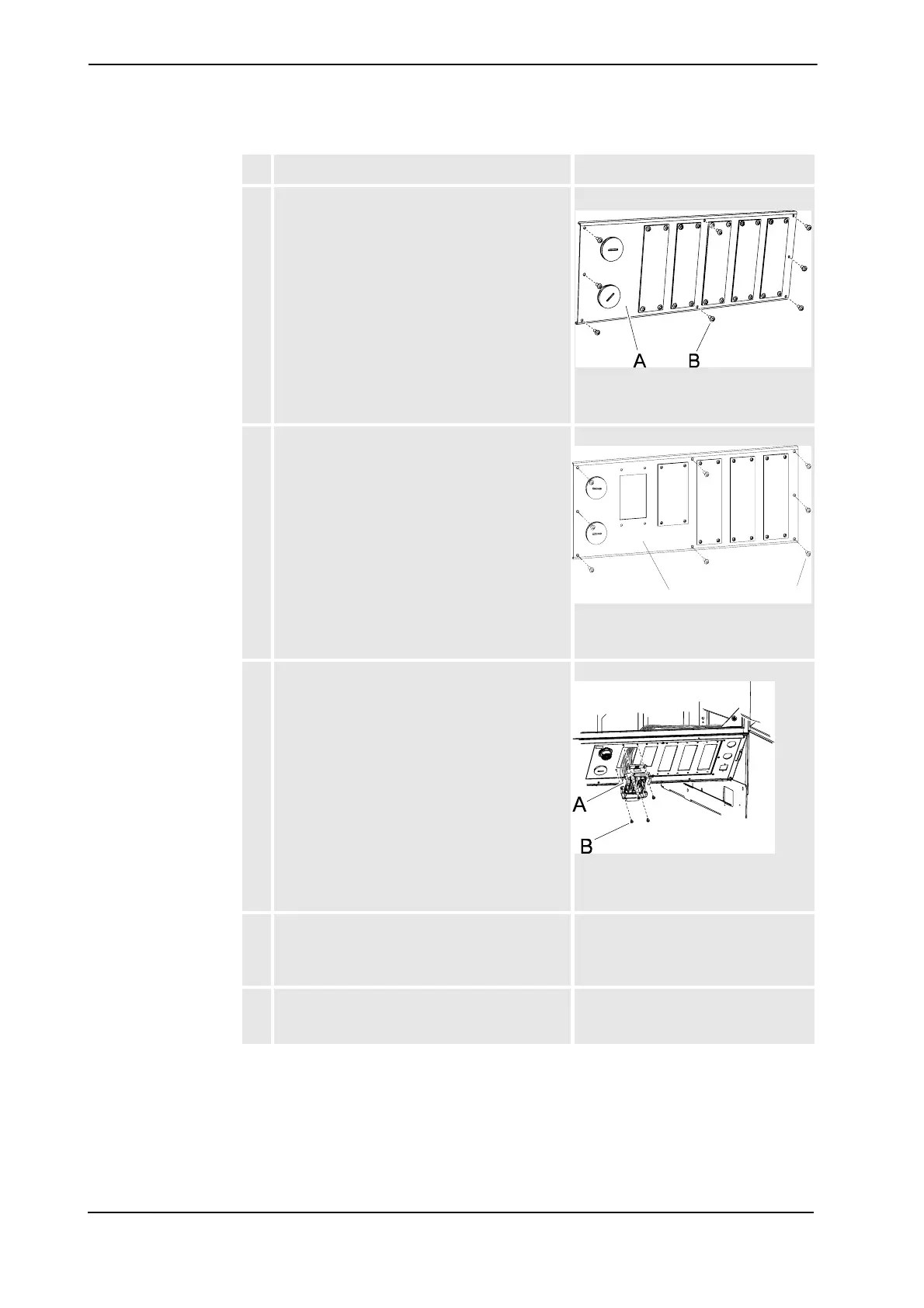
3. Remove the original adapter plate on the front
of the controller.
xx0600002652
• A: original adapter plate
• B: attachment screw (8 pcs)
4. Fit the included adapter plate.
xx0600002651
• A: Euromap adapter plate
• B: attachment screw (8 pcs)
5. Fit the harness through the connector hole on
the adapter plate, and fit the connector XS13
with the attachment screws.
xx0600002654
• A: connector XS13
• B: attachment screw (4 pcs)
6. Route the cables to I/O, fuse, relay and position
switch terminal mounted on the cabinet door
inside the cable protection according to the
illustration.
See Location of Euromap harness in
the Single Cabinet Controller on page
123.
7. Route the cables to the panel board connectors
in the existing straps according to the illustra-
tion.
See illustration Location of Euromap
harness in the Single Cabinet
Controller on page 123.
Action Note/Illustration
B
Continued
Continues on next page