2 Installation and Commissioning, IRC5
2.9.7. Installation of Euromap and SPI
1273HAC021313-001 Revision: K
© Copyright 2004-2008 ABB. All rights reserved.
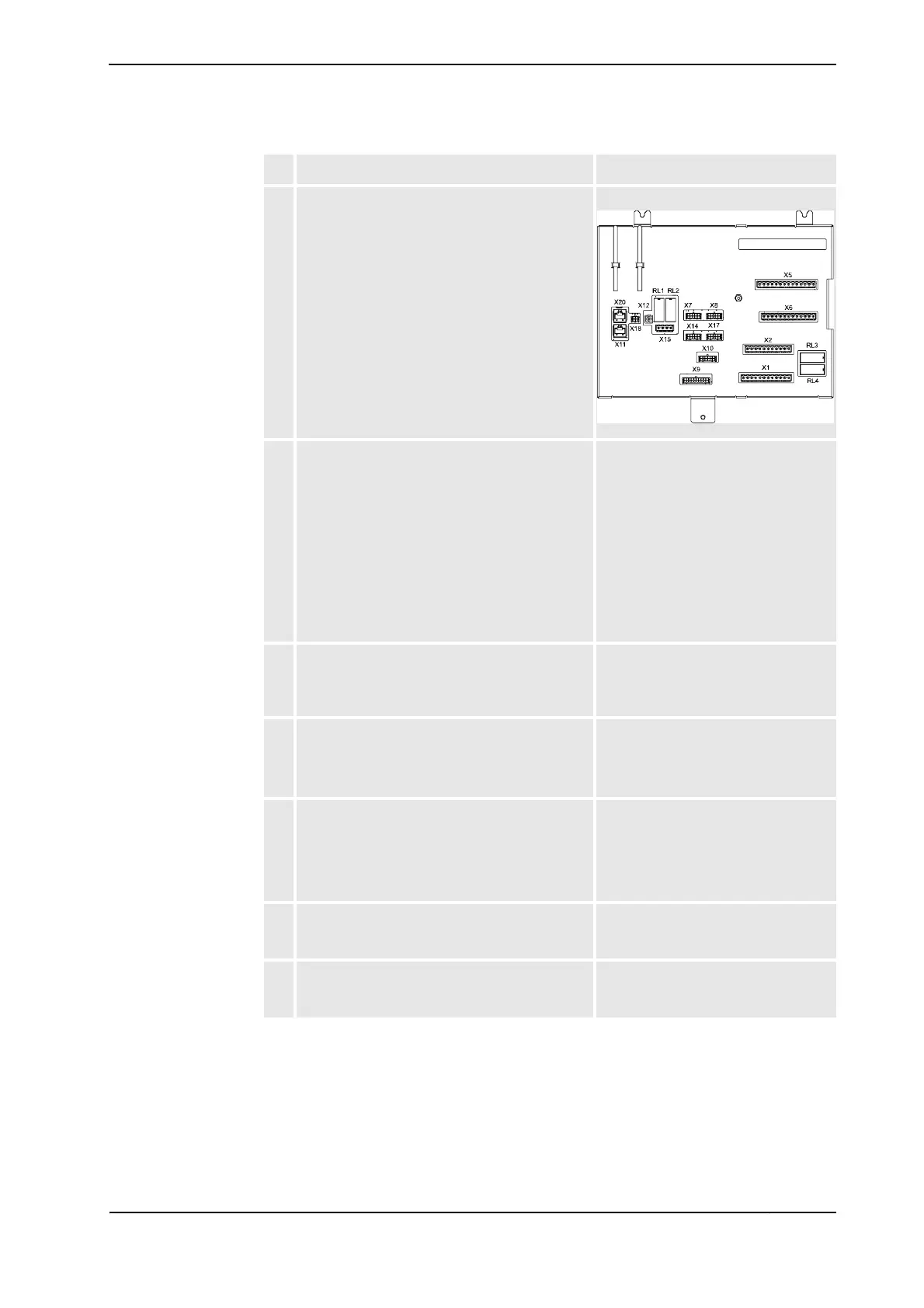
8. Connect the connectors X1, X2 and X5 on the
panel board.
xx0500001890
9. Connect the wires no. 1002 and no. 1019 to the
light barrier and safety relay.
"Mould area free" (Euromap) or
"Enable Clamp motion" (SPI) signal.
This important signal tells the injection
moulding machine (IMM) that nothing
is inside it’s workarea.
This signal can be connected in
several different ways, position
switches, I/O based world zones, etc.
We recommend that it is to connected
to a safety relay, controlled by light
barriers.
10. Connect the wires to the additional fuse:
•wire no. 1032 to XT31.2
•wire no. 1046 to XT31.4
See the location of the additional fuse
in Location of Euromap harness in the
Single Cabinet Controller on page
123.
11. Connect the wires between the additional fuse
and I/O 1.
• wire no. 1053 from XT31.6 to X1.10
• wire no. 1055 from XT31.8 to X1.9
See the location of the add. fuse and
I/O 1 in Location of Euromap harness
in the Single Cabinet Controller on
page 123.
12. Connect the wires to I/O 1.
•wire no. 1054 to X2.10
•wire no. 1056 to X4.9
•wire no. 1057 to X1.9
•wire no. 1058 to X2.9
See the location of I/O 1 in Location of
Euromap harness in the Single
Cabinet Controller on page 123.
13. Fit the 24K1 and 24K2 relays on the mounting
rail on the cabinet door.
See Location of Euromap harness in
the Single Cabinet Controller on page
123.
14. Connect the connectors X1, X2, X3 and X4 on
I/O 2.
See location of I/O 2 in Location of
Euromap harness in the Single
Cabinet Controller on page 123.
Action Note/Illustration
Continued
Continues on next page