Agilent 5DX Service Guide 8-11
5DX Series 3 Imaging Subsystem Components
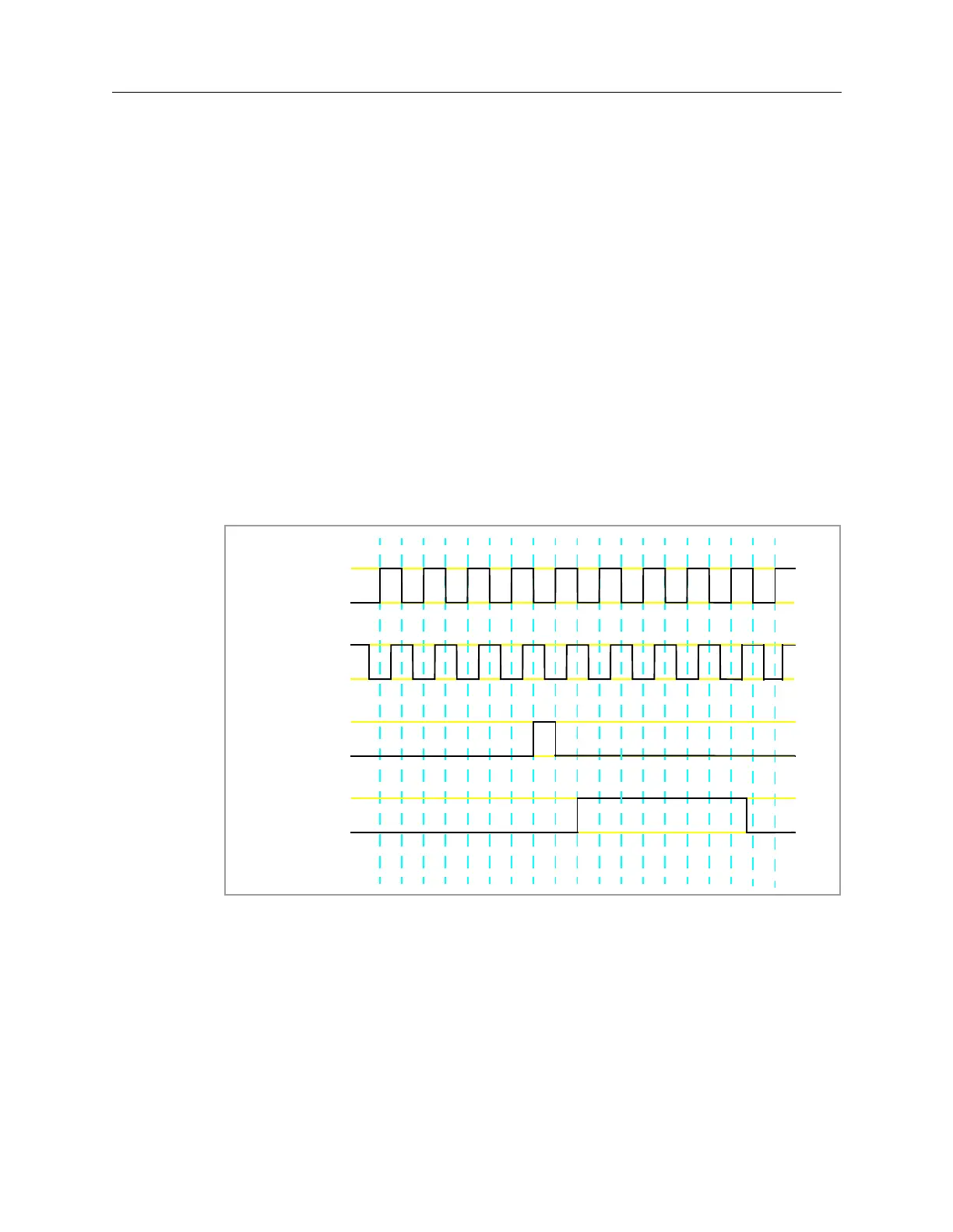
The X-ray Scan Controller receives the following input signals to determine the
position of the Rotary Scintillator Assembly.
Digital Rotary Encoder
• Pulse A and Pulse B — Used for incremental counting required to keep
the Electron Beam synchronized to the Rotary Scintillator. Also used to
determine the direction of rotation of the Rotary Scintillator Assembly.
• Z Pulse — Used to indicate that the Digital Rotary Encoder has
completed one revolution.
Scintillator Home Optical Sensor
• Scintillator Home Pulse — Used to indicate that the Rotary Scintillator
Assembly is at the Reference Home position. This is needed because
the Rotary Servomotor and the Digital Rotary Encoder rotate twice as
fast as the Rotary Scintillator.
A timing diagram showing the relationship of the signals is shown in Figure 8-5.
Figure 8-5: X-ray Scan Controller Input Signals
The X-ray Scan Controller decodes these signals and uses the resultant
information to activate the X and Y deflection coils. For each count issued by the
Digital Rotary Encoder, the X-ray Scan Controller increments or decrements the X
and Y beam deflection data by one count. A sine wave is generated as the X
deflection data increases and decreases. A second sine wave is generated as the Y
deflection data increase and decreases. A graphical representation of the resultant
X-Axis deflection and the Y-Axis deflection is shown in Figure 8-6.
Timing A
$FWLYH
1RW$FWLYH
Timing B
$FWLYH
1RW$FWLYH
Z
Scintilla-
tor Home
6FLQWLOODWRU+RPH
6FLQWLOODWRU1RW+RPH
$FWLYH
1RW$FWLYH
 Loading...

