Agilent 5DX Service Guide 3-17
5DX Series 3 Operator Control Console
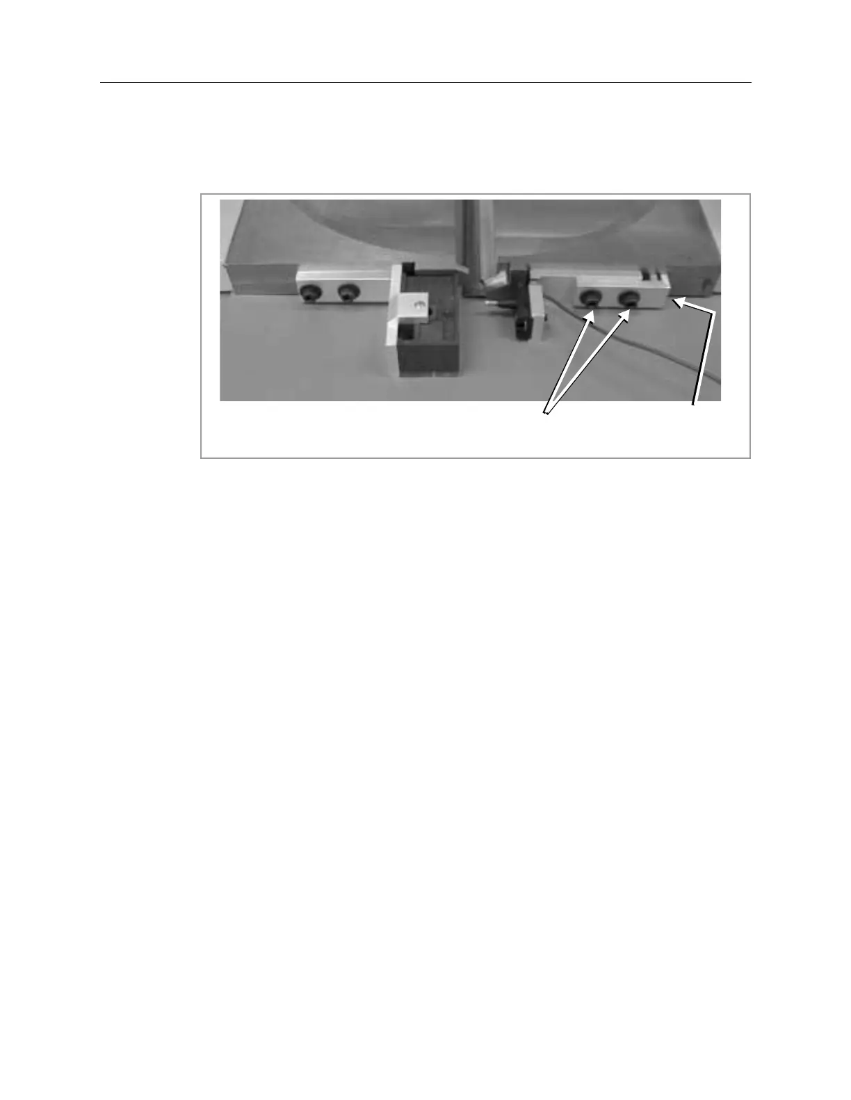
16. Using a 7/64-inch hex wrench, loosen the two bracket screws on the Safety
Interlock Pin Block, as shown in Figure 3-14. This is on the Right Half of the
Inner Barrier.
Figure 3-14: Pin Block Screw Locations
17. Using the 7/64-inch hex wrench positioned between the thumb and forefinger,
barely tighten the two bracket screws.
18. Use 5/64-inch hex wrench for the following:
a. Back out the Worm Screw until the ohmmeter indicates that the two pieces
of the Safety Interlock Switch are no longer making contact.
b. Turn the Worm Screw until it first makes contact.
c. Advance the Worm Screw an additional 1/4 turn more.
19. Tighten the two bracket screws.
20. Move the test leads for the ohmmeter to 2 and 5 on the Cable Adapter.
21. Repeat 16 through Step 19 for the Safety Interlock on the other side of the
Inner Barrier.
22. Insert the 50 mil side of the Gap Adjuster between the two halves of the Inner
Barrier. To do this, gently pull back on the Inner Barrier half and remove the
Gap Adjuster. Place the 50 mil side of the Gap Adjuster against the Tungsten
on the Inner Barrier half. Guide the Inner Barrier half back into position. The
force exerted by the Inner Barrier halves will hold the Gap Adjuster in place.
23. At this point the ohmmeter should show an open condition.
24. Move the test leads for the ohmmeter to 1 and 6. Again, the ohmmeter should
show an open condition.
Bracket Screws Worm Screw
 Loading...

