ConnectorConnector
Input modeInput mode
Switching between PDH Rx and DSn Rx is done in the SDH/SONET receiver
setup screen.
1. Select SDH RxSDH Rx or SONET RxSONET Rx check box.
2. Touch STM-xxSTM-xx, STS-xxSTS-xx, or OC-xxOC-xx button in the navigation area.
3. Use drop down menu at right bottom to switch SDH or SONET. Selecting the
SDH displays PDH RxPDH Rx on RxRx screen. Selecting the SONET displays DSn RxDSn Rx on
RxRx screen.
4. Touch RxRx button in the navigation area.
5. Select PDH RxPDH Rx or DSn RxDSn Rx check box.
6. Clear SDH RxSDH Rx or SONET RxSONET Rx check box.
7. Touch E1E1 radio button. Touching OffOff radio button disables the receiver.
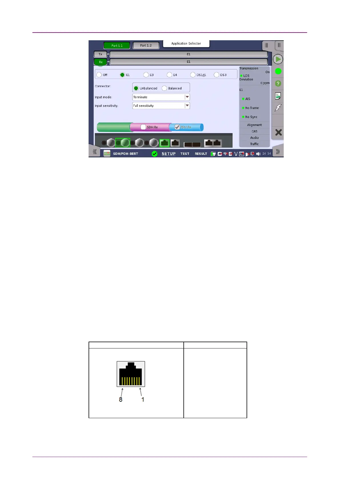
This screen allows you to make the physical setup of the PDH receiver in E1
mode. It can also be used to inspect the current status of the selected port.
The configuration options available in the setup area of the screen are
described below. The status information is described in a separate section.
Select the physical type of the relevant output connectors located on the back
panel of the instrument. Choose UnbalancedUnbalanced to link to the corresponding
unbalanced connector, or choose BalancedBalanced to link to the corresponding
balanced connector. A balanced input is taken from RJ48 connector.
Pin assignment of E1 Balanced ConnectorsPin assignment of E1 Balanced Connectors
RJ-48 PinRJ-48 Pin SignalSignal
1 RX, Ring
2 RX, Tip
3 Ground
4 TX, Ring
5 TX, Tip
6 Ground
7 No connect
8 No connect
Be sure to confirm the cable type. For E1 cable, there are the straight cable and
the cross cable.
Select the mode of input.