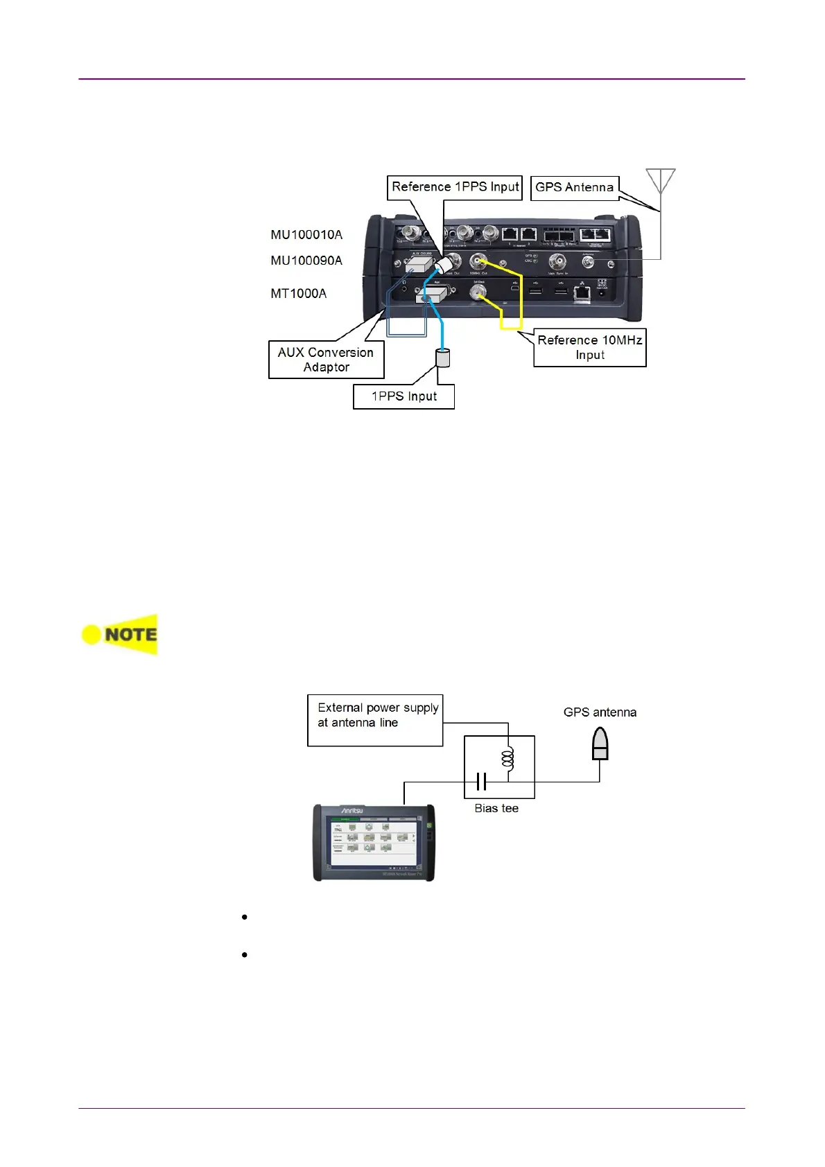
Connections of GPS Disciplined Oscillator Interfaces are shown below.
Use GPS antenna, BNC cables and J1705A AUX Conversion Adaptor for the
connections.
1. Connect J1706A GPS antenna to Antenna connector on the MU100090A.
Commercially available GPS antenna can be used.
2. Connect AUX DSUB9 of the MU100090A to AUX of the MT1000A using
J1705A AUX Conversion Adaptor.
3. Connect 10MHz Out of the MU100090A to Sync In of the MT1000A using
J1710A BNC Cable.
4. Connect 1PPS Out of the MU100090A to REF 1PPS IN of J1705A AUX
Conversion Adaptor.
5. Input the signal under measurement to 1PPS IN of J1705A AUX Conversion
Adaptor.
When performing the measurements using GPS time by capturing GPS satellites, wait 30
minutes or more for the synchronization after capturing GPS satellites.
If waiting time for synchronization is short, the correct time will not be obtained.
When feeding the power to a GPS antenna using external power supply, insert a bias tee
between the GPS antenna and MU100090A.
Select a bias tee which meets the MU100090A specifications below:
Antenna connector: SMA, Jack (refer to 12.4.2 "Electrical performance and
function")
Supported signal: GPS L1 C/A Code (refer to 12.4.3 "GPS Synchronization")