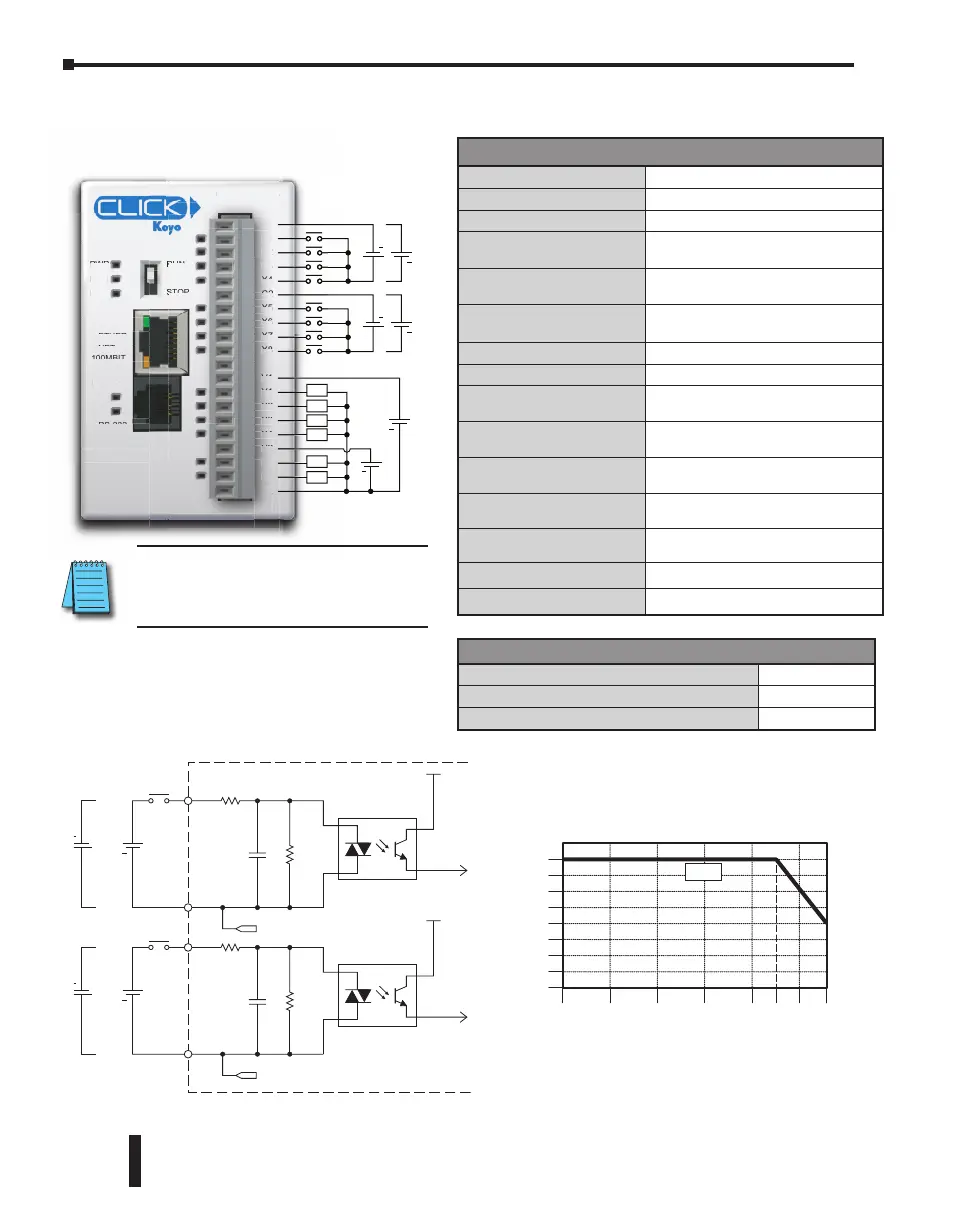
C0-10DD2E-D
C1
X1
X2
X3
X4
C2
X5
X6
X7
X8
V1
Y1
Y2
Y3
Y4
V2
Y5
Y6
CO
LNK/ACT
PORT1
PWR
RUN
ERR
RUN
STOP
PORT2
RS-232
TX2
RX2
100MBIT
ETHER
NET
+ +
++
24VDC
+
L
+
24VDC
L
L
L
L
L
Y
D2E
-1
D
RT2
-
X
X
NK
A
T
RT1
0
Surrounding Air Te mperature (°C/°F)
32
10
50
20
68
30
85
40
104
50
122
55 °C
131
2
4
6
8
C0-10DD2E-D Temperature Derating Chart
0
45
113
Inputs
*
INPUT
X1-X4
Typical
COM
Internal Module Circuitry
Optical Isolator
24 VDC
+
INPUT
X5-X8
Typical
COM
Optical Isolator
24 VDC
+
C1
C2
To X6-X8
commons
To X2-X4
commons
Wiring Diagram
General Specifications
Current Consumption at 24VDC
120mA
Terminal Block Replacement Part No.
C0-16TB
Weight
5.0 oz (140g)
Built-in I/O Specifications - Inputs
Inputs per Module
8 (Sink/Source)
Operating Voltage Range
24VDC
Input Voltage Range
21.6–26.4 VDC
Input Current
X1-4: Typ 6.5 mA @ 24VDC
X5-8: Typ 4mA @ 24VDC
Maximum Input Current
X1-4: 7.0 mA @ 26.4 VDC
X5-8: 5.0 mA @ 26.4 VDC
Input Impedance
X1-4: 3.9 kΩ @ 24VDC
X5-8: 6.8 kΩ @ 24VDC
Input Frequency (Max)
X1-X4: 100kHz
ON Voltage Level
> 19VDC
OFF Voltage Level
X1-4: < 2VDC
X5-8: < 7VDC
Minimum ON Current
X1-4: 4.5 mA
X5-8: 3.5 mA
Maximum OFF Current
X1-4: 0.5 mA
X5-8: 1.5 mA
OFF to ON Response
X1-4: Typ 3μs Max 5μs
X5-8: Typ 2ms Max 10ms
ON to OFF Response
X1-4: Typ 1μs Max 3μs
X5-8: Typ 3ms Max 10ms
Status Indicators
Logic Side (8 points, green LED)
Commons
2 (4 points/common) Isolated
C0-10DD2E-D – 8 DC Input/6 Sourcing DC Output Micro PLC
NOTE: When using Ethernet Basic PLCs,
you must use CLICK programming
software version V2.00 or later.
X1-X4 Inputs
High-Speed
CLICK PLC Hardware User Manual, 6th Edition, Rev. G – C0-USER-M
2–62
Chapter 2: Specifications

 Loading...