NOTE: In the circuit above, the current in the common path is equal to the sum of the energized channels.
This is especially important in output circuits, where larger gauge wire is sometimes needed for the
commons.
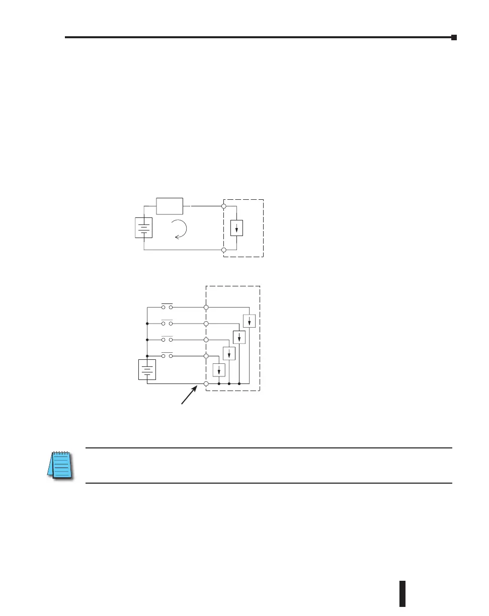
I/O “Common Terminal” Concepts
In order for a PLC I/O circuit to operate, current must enter at one terminal and exit at
another. This means at least two terminals are associated with every I/O point. In the figure
to the right, the input or output terminal is the main path for the current. One additional
terminal must provide the return path to the power supply.
If there was unlimited module space, then every I/O point could have two dedicated terminals
as the figure above shows. Providing this level of flexibility is not practical or necessary for most
applications. So, most I/O point groups share the return path (common) among two or more
I/O points. The figure to the right shows a group (or bank) of 4 input points which share a
common return path. In this way, the four inputs require only five terminals instead of eight.
+
–
I/O
Circuit
Return Path
Main Path
(I/O point)
Field
Device
PLC
+
–
Input Sensing
Input 4
Common
Input 3
Input 2
Input 1
Electrical Common
To All Input Points
CLICK PLC Hardware User Manual, 5th Edition, Rev. F – C0-USER-M
3–29
Chapter 3: Installation and Wiring

 Loading...