Input Specifications
Inputs per Module
4 (source/sink)
Operating Voltage Range
CE: 12–24 VDC (-10%/+10%)
UL: 12–24 VDC (-10%/+10%)
Input Voltage Range
10.8–26.4 VDC
Input Current
Typ 5.0 mA @ 24VDC
Maximum Input Current
7.0 mA @ 26.4 VDC
Input Impedance
4.7 kq @ 24VDC
ON Voltage Level
>8.0 VDC
OFF Voltage Level
<3.0 VDC
Minimum ON Current
1.4 mA
Maximum OFF Current
0.5 mA
OFF to ON Response
Max. 3.5 ms Typ 2ms
ON to OFF Response
Max. 4ms Typ 2.5 ms
Status Indicators
Logic Side (4 points, green LED)
Power Indicator (green LED)
Commons
1 (4 points/common)
General Specifications
Bus Power Required (24VDC)
Max. 80mA (all points on)
Protection Circuit
Not built into the module - Install
protection elements such as
external fuse
Terminal Block Replacement
AutomationDirect p/n C0-8TB
Weight
3.2 oz (90g)
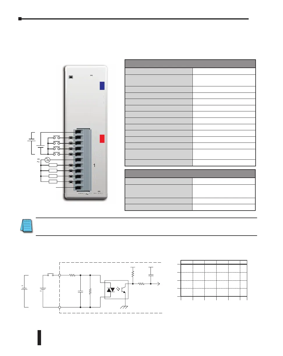
C0-08CDR – 4-Point DC Input and 4-Point Relay Output Module
4-point 12–24 VDC current sinking/sourcing input, 1 common, 4-point 6.25–24 VDC /
6–240 VAC relay output, Form A (SPST) relays 1A/pt, 1 common, non-fused, removable
terminal block included.
C1
1
2
3
4
C2
1
2
3
4
C0-08CDR
PWR
12-24V 2.5-5mA
INPUT
OUTPUT
250V 1A 50-60Hz
30V 1A
1
-
-
4
.5-5mA
NP
T
OUTPUT
12-24VDC
+
–
+
–
L
L
L
L
240VAC
24VDC
N.C.
N.C. = Not Connected
Wiring Diagram
0
Surrounding Air Temperature (°C/°F)
32
10
50
20
68
30
85
40
104
50
122
55 °C
131 °F
1
2
3
4
o
nts
Input Temperature Derating Chart
0
INPUT
COM
Internal Module Circuitry
Optical Isolator
12-24 VDC
+
+
NOTE: When using this module you must also use CLICK programming software and PLC firmware
version V1.40 or later.
CLICK PLC Hardware User Manual, 6th Edition, Rev. G – C0-USER-M
2–134
Chapter 2: Specifications

 Loading...