EasyManuals Logo

AutomationDirect CLICK Series User Manual

AutomationDirect CLICK Series
301 pages
To Next Page IconTo Next Page
To Previous Page IconTo Previous Page
Page #30 background imageLoading...
Page #30 background image
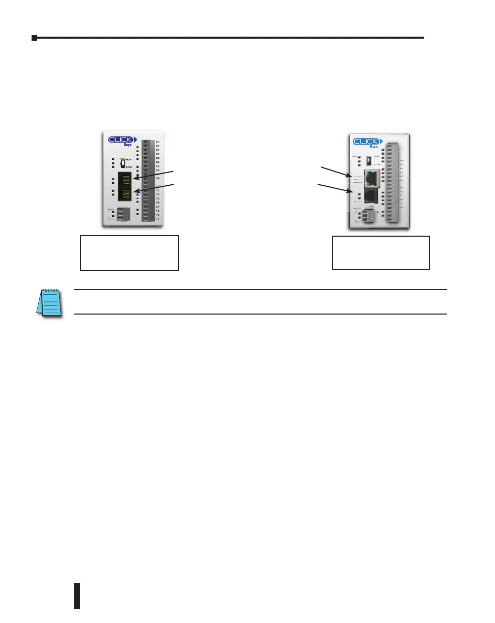
Step 6: Establish PC to PLC Communications
Next, connect a personal computer (PC) to Port 1 or Port 2 on the CLICK PLC unit. You
can use one of the following communication ports on the CLICK PLC unit for programming.
RS-485
+
_
LG
C0-11DD1E-D
C1
X1
X2
X3
X4
C2
X5
X6
X7
X8
C3
Y1
Y2
Y3
Y4
C4
Y5
Y6
+V
LNK/ACT
PORT1
PWR
RUN
ERR
RUN
STOP
PORT2
PORT3
RS-232
TX2
RX2
100MBIT
ETHER
NET
TX3
RX3
7
X7
7
X7
8
X8
8
X8
3
C3
3
C3
2
Y2
2
Y2
3
Y3
3
Y3
4
Y4
4
Y4
4
C4
4
C4
5
Y5
6
Y
6
V
+V
NET
D
-D
D1E
-
1
C1
X1
2
X2
3
X3
4
X4
4
X4
2
C2
2
C2
5
X5
5
X5
6
X6
6
X6
7
X7
C
0-11D
R
R
RUN
RUN
S
STOP
STO
P
S
STOP
G
L
G
_
_
+
+
100MBI
T
NET
P
O
RT
2
TX
2
RX2
100MBI
T
100MBI
T
RS
-
232
RS
232
T
X
X3
R
X
X3
PO
OR
T3
RS-
PO
OR
T3
-485
5
485
5
ETH
ER
NET
ETH
ER
L
NK
/
A
C
T
P
O
RT
1
PWR
PWR
R
U
N
ER
R
R
R
S
S
S
S
C0-01DD1-D
RS-485
PORT3
PORT2
PORT1
PWR
RUN
ERR
TX2
RX2
TX1
RX1
TX3
RX3
C0
-
0
1DD1-
D
RS
-4
85
PO
RT
3
PO
RT
2
P
ORT
1
P
W
R
RU
N
E
R
R
TX
2
R
X
2
TX
1
R
X
1
TX
3
R
X
3
Basic PLC
Standard PLC
Analog PLC
Ethernet Basic PLC
Ethernet Standard PLC
Ethernet Analog PLC
Port 1 (RS-232)
Port 2 (RS-232)
Port 1 (Ethernet)
Port 2 (RS-232)
NOTE: Port 2 (RS-232) setup can be changed by the customer. We recommend using Port 1 for
Programming.
CLICK PLC Hardware User Manual, 6th Edition, Rev. G – C0-USER-M
1–16
Chapter 1: Getting Started

Table of Contents

Questions and Answers:

Question and Answer IconNeed help?

Do you have a question about the AutomationDirect CLICK Series and is the answer not in the manual?

AutomationDirect CLICK Series Specifications

General IconGeneral
BrandAutomationDirect
ModelCLICK Series
CategoryController
LanguageEnglish

Related product manuals