C0-4AD2DA-2 – 4-Channel Analog Voltage Input and 2-Channel Analog
Voltage Output Module (continued)
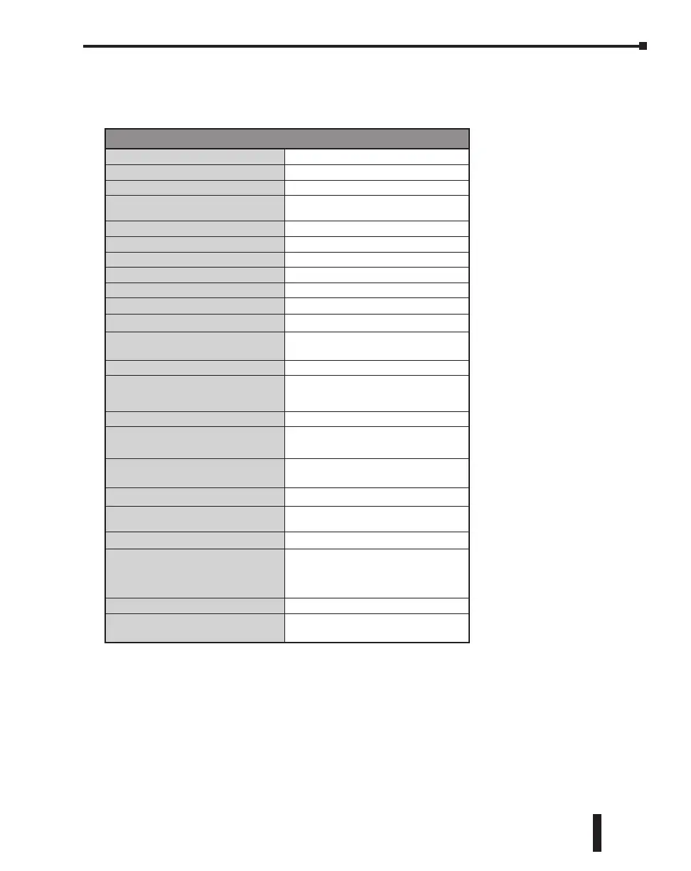
Output Specifications
Outputs per Module
2
Output Range
0–10 V
Resolution
12-bit, 2.44 mV per count
Output Type
Voltage sourcing at 10mA max.
(One common)
Output Value in Program Mode
Determined by PLC
Output Value in Fault Mode
0V
Output Impedance
0.2 q typical
Load Impedance
>1000q
Maximum Capacitive Load
0.01 μF maximum
Allowed Load Type
Grounded
Maximum Inaccuracy
1% of range
Max. Full Scale Calibration Error
(Not including Offset)
±0.2% of range maximum voltage
Max. Offset Calibration Error
±0.2% of range maximum
Accuracy vs. Temperature
±75 PPM/°C maximum full scale
calibration change (±0.0025% of
range/°C)
Max. Crosstalk at DC, 50/60 Hz
-72dB, 1 LSB
Linearity Error (End to End)
±4 LSB maximum, (±0.1% of full scale);
monotonic with no missing codes
Output Stability and
Repeatability
±2% LSB after 10 minute warmup period
typical
Output Ripple
0.5% of full scale
Output Settling Time
0.3 ms maximum,
5μs minimum (full scale range)
All Channel Update Rate
20ms
Max. Continuous Overload
Outputs current limited to 40mA typical;
continuous overloads on multiple outputs
can damage
module.
Type of Output Protection
0.1 μF transient suppressor
Output Signal at Power Up or
Power Down
0V
CLICK PLC Hardware User Manual, 6th Edition, Rev. G – C0-USER-M
2–147
Chapter 2: Specifications