Enclosures
Your selection of a proper enclosure is important to ensure safe and proper operation of
your CLICK PLC system. Control applications vary and yours may require additional
considerations. At a minimum your enclosure should include:
• Conformance to electrical standards
• Protection from the elements in an industrial environment
• Common ground reference
• Maintenance of specified ambient temperature
• Access to equipment
• Security or restricted access
• Sufficient space for proper installation and maintenance of equipment
Panel Layout and Clearances
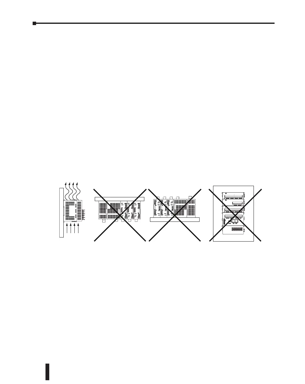
1. Mount the CLICK PLC unit (system) horizontally as shown below to provide proper
ventilation. Do not mount the CLICK PLC units upside down, on a horizontal surface
or in a vertical arrangement. If you place more than one unit in a cabinet, there must be a
minimum of 7.2” (183mm) between the units.
2. Provide a minimum clearance of 2” (50mm) between the unit and all sides of the cabinet.
NOTE: Remember to allow clearance for any operator panels or other items mounted
directly in front of the unit in the door.
3. There should also be at least 3” (78mm) of clearance between the unit and any wiring ducts
that run parallel to the terminals.
4. The ground terminal on the CLICK PLC must be connected to a single point ground. Use
copper stranded wire to achieve a low impedance. Copper eye lugs should be crimped and
soldered to the ends of the stranded wire to ensure good surface contact.
5. There must be a single point ground (i.e. copper bus bar) for all devices in the panel
requiring an earth ground return. The single point of ground must be connected to the
panel ground termination. The panel ground termination must be connected to ground.
Minimum wire sizes, color coding, and general safety practices should comply with
appropriate electrical codes and standards for your area.
Air
TX2
PORT2
PORT1
RX2
RX1
TX1
PWR
ERR
RUN
STOP
RUN
CLICK PLC Hardware User Manual, 5th Edition, Rev. F – C0-USER-M
3–14
Chapter 3: Installation and Wiring

 Loading...