I/O Numbering System
The CLICK PLC uses decimal numbers for the input (X) and output (Y) addressing.
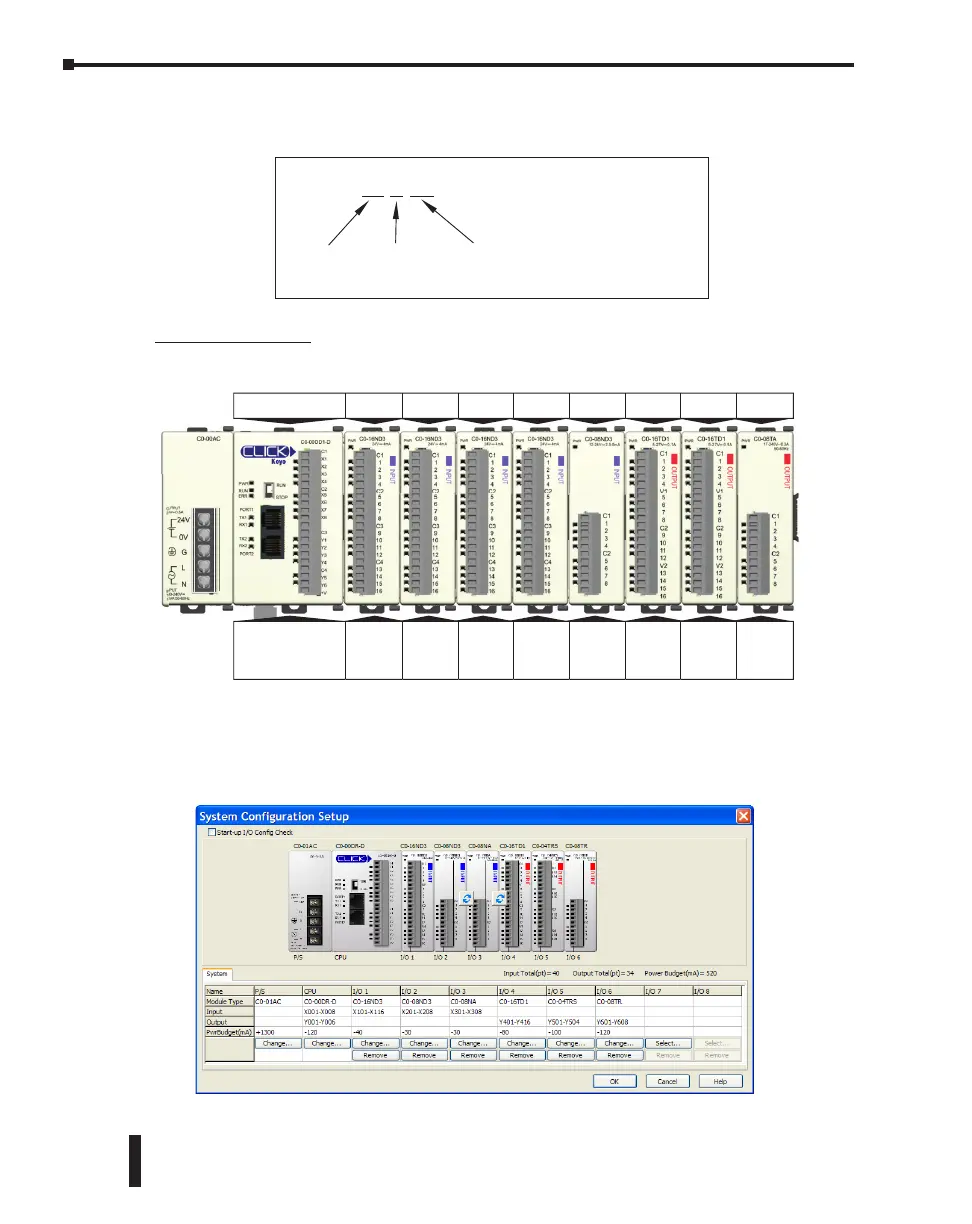
Module Location
Please refer to the following diagram to understand the module position and I/O numbering.
The
I/O
Addressing can be checked by using the System Configuration window from within the
CLICK programming software. From the Setup pulldown menu, select System Configuration;
otherwise, from the Navigation window select the Function tab, and under PLC configuration,
double click on System Configuration.
X216
X: Input
Y: Output
Module
Position
(0-8)
I/O Point #
on the module
(01-16)
For example, address X216 means
the 16
th
input point on the second
module from the CPU module.
0 12345678
Position
I/O
Address
PLC
X001
―
X008
Y001
―
Y006
X101
―
X116
X201
―
X216
X301
―
X316
X401
―
X416
X501
―
X508
Y601
―
Y616
Y701
―
Y716
Y801
―
Y808
CLICK PLC Hardware User Manual, 6th Edition, Rev. G – C0-USER-M
2–18
Chapter 2: Specifications

 Loading...