General Specifications
Field to Logic Side Isolation
1800 VAC applied for 1 second
(100% tested)
External DC Power Required
None
Bus Power Required (24VDC)
25mA
Thermal Dissipation
0.175 BTU per hour
Terminal Block Replacement
AutomationDirect p/n C0-8TB
Weight
3.1 oz (86 g)
Input Specifications
Inputs per Module
4
Common Mode Range
-1.3 to +3.8 V
Common Mode Rejection
100dB at DC and 130dB at 60Hz
Input Impedance
>5Mq
Maximum Ratings
Fault protected inputs to ±50VDC
Resolution
±0.1°C or °F, 16-bit
Input Ranges
Type J: -190 to 760ºC (-310 to 1400ºF)
Type K: -150 to 1372ºC (-238 to 2502ºF)
Type E: -210 to 1000ºC (-346 to 1832ºF)
Type R: 65 to 1768ºC (149 to 3214ºF)
Type S: 65 to 1768ºC (149 to 3214ºF)
Type T: -230 to 400ºC (-382 to 752ºF)
Type B: 529 to 1820ºC (984 to 3308ºF)
Type N: -70 to 1300ºC (-94 to 2372ºF)
Type C: 65 to 2320ºC (149 to 4208ºF)
0 to 39.0625 mV
±39.0625 mV
±78.125 mV
0 to 156.25 mV
±156.25 mV
0 to 1.25 V
NOTE: When using this module you
must also use CLICK programming
software and PLC firmware version
V1.40 or later.
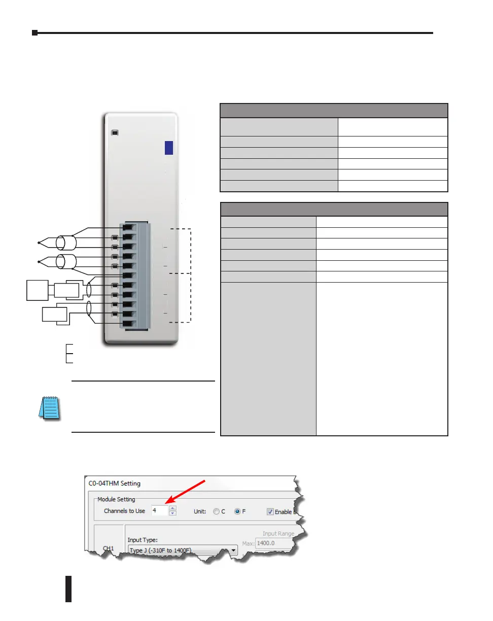
C0-04THM – 4-Channel Thermocouple Input Module
4-channel thermocouple input module, 16-bit resolution (±0.1 degrees Celsius or Fahrenheit),
Supports: J, K, E, R, S, T, B, N, C type thermocouples; voltages ranges also supported,
removable terminal block included.
COM
TC1+
TC1–
TC2+
TC2–
COM
TC3+
TC3–
TC4+
TC4–
COM
C0-04THM
J,K,E,R,S,T,B,N,C,mV
INPUT
*Cannot exceed common-mode
All ‘COM’
connected
internally.
M
1+
1
2+
M
C3+
3
4+
4
M
K
E
R
T
B
N
mV
NPU
TCn+
TCn-
COM
Connect
unused
channels
mV
Device
*
Device
Power
Supply
mV
Device
*
Shield
Wiring Diagram
If there are any unused channels, make sure to select the correct number of channels that you
actually use in the C0-04THM Setting window.
CLICK PLC Hardware User Manual, 6th Edition, Rev. G – C0-USER-M
2–140
Chapter 2: Specifications

 Loading...