C0-04THM – 4-Channel Thermocouple Input Module (continued)
Input Specifications (continued)
Cold Junction Compensation
Automatic
Thermocouple Linearization
Automatic
Accuracy vs. Temperature
±25 ppm per °C maximum
Linearity Error
±2°C maximum, ±1°C typical,
monotonic with no missing codes
Maximum Inaccuracy
±3°C maximum (excluding
thermocouple error)
Maximum Voltage Input Offset
Error
0.05% at 0° to 55° C (32° to 131° F),
typical 0.04% at 25° C (77° F)
Maximum Voltage Input Gain
Error
0.06% at 25°C (77°F)
Maximum Voltage Input
Linearity Error
0.05% at 0° to 55°C (32° to 131°F),
typical 0.03% at 25°C (77°F)
Maximum Voltage Input
Inaccuracy
0.1% at 0° to 55°C (32° to 131°F),
typical 0.04% at 25°C (77°F)
Warm Up Time
30 minutes for ±1C° repeatability
Single Channel Update Rate
400ms
All Channel Update Rate
Single Channel Update Rate times
the number of enabled channels on
the module
Open Circuit Detection Time
Burn Out flag set and zero scale
reading within 3 seconds
Conversion Method
Sigma - Delta
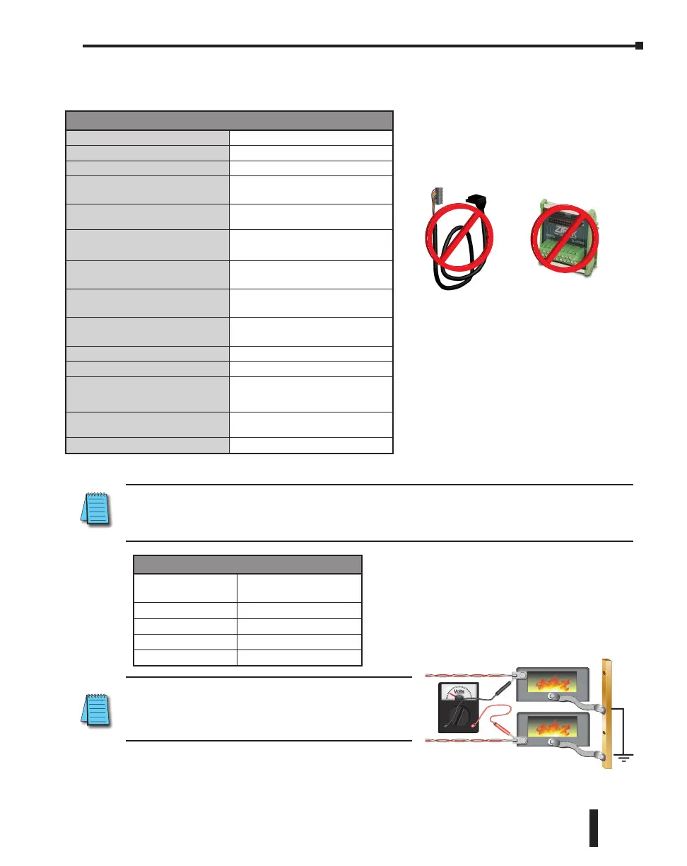
Not Compatible with ZIPLink Pre-Wired PLC
Connection Cables and Modules.
Initialization Time
The Number of
Channels Used
With any Configuration
1 5 sec
2 7 sec
3 9 sec
4 11 sec
NOTE: With grounded thermocouples, take precautions to
prevent having a voltage potential between thermocouple
tips. A voltage less than -1.3V or greater than +3.8V
between tips will skew measurements.
NOTE: When this module is used in a CLICK PLC system, it takes up to 11 seconds for initialization after
power-up. During this time period, the RUN LED on the PLC module blinks to indicate the initialization
process.
CLICK PLC Hardware User Manual, 6th Edition, Rev. G – C0-USER-M
2–141
Chapter 2: Specifications

 Loading...