Error Codes
When there is an Error or Warning, the error code is stored in the System Data register SD1.
When an Error occurs during the operation, the CLICK PLC system goes to the STOP mode
immediately and the ERR LED on the PLC unit turns on. On the other hand, when a
Warning occurs during the operation, the CLICK PLC system stays in RUN mode and the
ERR LED on the PLC unit starts blinking.
In the error code tables that follow, the Category column indicates whether the error code is
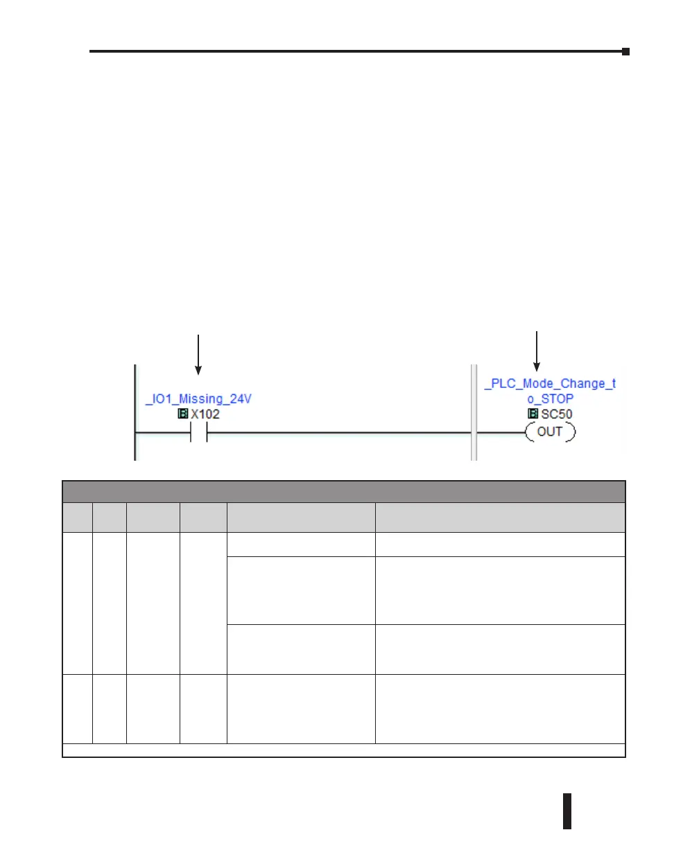
an Error or a Warning. If any of the Warnings listed is critical for your control system, add an
additional ladder program to put the CLICK PLC system in STOP mode when that specific
Warning occurs. Here is an example.
Example
PLC Error Codes
Error
Code
Status
Flag*
Error
Name
Category Causes Solutions
101 SC20
I/O Module
Error
Error
There are more than 8 I/O
modules.
A CLICK PLC system can support up to 8 I/O modules.
Remove any excessive I/O modules.
At least one I/O module was
added to the CLICK PLC during
operation.
Power off the CLICK PLC and check the connection of the
I/O modules. Then power on the CLICK PLC again. If the
problem remains, connect the CLICK software to the PLC
and check the System Configuration. If there is any I/O
module that is not shown in the System Configuration,
replace it.
An I/O module has failed.
Connect the CLICK software to the CLICK PLC and check
the system configuration. If there is any I/O module that
is used in the PLC system but not shown in the System
Configuration window, replace the I/O module.
102 SC21
System
Config
Error
Error
The current system configuration
does not match the configuration
saved in the project file.
Connect the CLICK software to the CLICK PLC and open
the System Configuration window. Modify the current
configuration of the CLICK PLC to match the configuration
in the project file, or uncheck the ‘Start-up I/O Config
Check’ option if you want to use the current configuration.
* The Status Flags are turned ON when the related errors occur.
Error code table continued on next page.
X102 turns on when the analog
I/O module in the I/O1 position is
missing external 24VDC input.
By turning the System Control bit
SC50 on, the CLICK PLC system
goes in the STOP mode.
CLICK PLC Hardware User Manual, 6th Edition, Rev. F – C0-USER-M
6–11
Chapter 6: Troubleshooting

 Loading...